Assembling a Foowin freestanding propane patio heater takes about 50 minutes, works best with two people for the taller pole sections, and follows a straightforward sequence: build the base, stack and secure the pole sections, mount the burner head and reflector, route the gas hose, then do a soapy-water leak test before you ever touch the igniter. The instructions below walk you through every step, including the fastener and alignment details that the box instructions tend to skim over.
Foowin Patio Heater Assembly Instructions: Step Guide

Grant Mercer
23 Jul 2026
What this guide covers
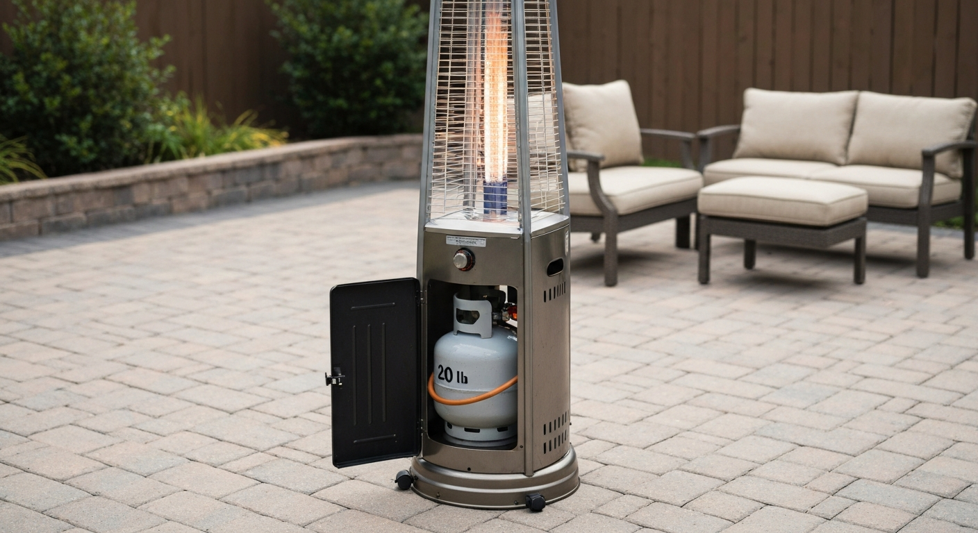
Foowin sells a 48,000 BTU tower-style (sometimes called pyramid or umbrella) propane patio heater that stands roughly 90 to 91 inches tall on an 18-inch base and weighs about 58 pounds fully assembled. The heater runs on a standard 20 lb LP cylinder stored inside the base compartment. This guide covers the full assembly sequence for that freestanding model, plus the gas connection, leak test, first-light procedure, and the post-assembly troubleshooting you are most likely to need: pilot that won't light, pilot that won't stay lit, a tripping tilt switch, and a failing thermocouple. If you are assembling a different brand, the process is similar enough that guides for comparable models like East Oak, Hampton Bay, Mainstays, Pamapic, or Pyramid heaters can fill in gaps where part names differ.
Safety before you touch anything
Propane is heavier than air, which means any leak pools at ground level rather than dissipating upward. Do all assembly and leak testing outdoors, away from ignition sources, open flames, electrical outlets, and enclosed spaces. Keep a working fire extinguisher rated for Class B fires within reach during your first light-up. Never use a flame to test for gas leaks. This is not a suggestion, it is a rule backed by federal LPG safety code (46 C.F.R. §58.16-30) and every manufacturer manual in this category. Soapy water only.
The Foowin heater includes a tip-over protection circuit: if the heater tilts beyond roughly 45 degrees, an automatic shutoff activates. This is a gravity-actuated mechanical tilt switch (commonly an FD4-style dump switch) wired in series with the gas valve. It is a safety feature, not a fault, so do not try to bypass it. If it trips during normal upright use, that is a diagnostic clue covered in the troubleshooting section below. The heater also has a flame-out protection sensor (thermocouple or thermopile) and an anoxic/low-oxygen sensor, so the unit will shut down if the pilot flame goes out or if oxygen levels drop below safe operating limits.
- Wear cut-resistant gloves when handling sheet-metal edges on the reflector and burner housing.
- Wear safety glasses during assembly, especially when threading fasteners overhead.
- Do not assemble or operate the heater indoors, in a garage, on a covered porch with limited airflow, or under a low ceiling.
- The Foowin manual specifies outdoor use only and a minimum clearance to combustibles. Check your specific model's documentation for the exact number. A common published reference is 24 to 36 inches of radial clearance and at least 36 inches of overhead clearance, but always confirm against your model's spec sheet.
- Keep children and pets away from the work area during assembly and the first test fire.
- If you smell gas at any point, stop immediately, move away from the heater, and do not use any electrical switches until the area has fully ventilated.
Parts you should have out of the box
Before you start, lay everything out on a clean, flat surface and check it against the packing list in your Foowin manual. Missing a gasket or a locking washer now is a lot less frustrating than discovering it mid-assembly. Here is what the standard Foowin tower heater package includes:
| Part | Qty (typical) | Notes |
|---|---|---|
| Base frame / housing with casters | 1 | Casters may be packed separately; check the base compartment |
| Lower pole section | 1 | Larger diameter; houses gas hose routing channel |
| Upper pole section(s) | 1–2 | Align carefully, orientation matters for hose clearance |
| Burner head assembly (burner module / IR plate) | 1 | Do not drop; the ceramic emitter is fragile |
| Top reflector (dome / heat reflector) | 1 | Includes reflector studs or mounting clips |
| Quartz glass flame tube | 1 | Fragile; keep in packaging until needed |
| Protective mesh / wire guard | 1 | Fits around quartz tube at burner level |
| Pilot / igniter assembly (integrated with control box on most models) | 1 | Already attached to control valve in most Foowin units |
| Thermocouple or thermopile lead | 1 | Usually pre-routed to pilot hood; confirm seating |
| Gas hose and low-pressure regulator assembly | 1 | Pre-assembled; confirm no kinks or crimps |
| Fastener pack (bolts, nuts, washers, lock washers) | 1 pack | Count and sort before starting |
| Gaskets (burner and hose connection) | 2–3 | Soft-seal; do not reuse if deformed |
| Hardware bag with caster bolts | 1 | Often tucked inside base |
If any part is missing, cracked, or visibly damaged, contact Foowin support before proceeding. Operating with a damaged quartz tube or a compromised regulator hose is a real safety risk, not just an inconvenience. Replacement part names for Foowin components map closely to the names used by East Oak and Hiland-style pyramid heaters, so cross-referencing those parts lists can help you identify what to order.
Tools you will need
- Adjustable wrench or combination wrench set (10 mm, 12 mm, and 13 mm cover most fittings on these heaters)
- Phillips and flathead screwdrivers
- Torque wrench (optional but recommended for burner head fasteners; if you use one, target 7 to 12 N·m / 5 to 9 lbf·ft for M6 hardware as a general reference when the manual does not specify a value)
- Needle-nose pliers (helpful for routing the thermocouple lead through pole sections)
- Bubble level or level app on your phone (for final placement check)
- Leak-detection solution: mix 1 part dish soap to 3 parts water in a small squeeze bottle, or use commercial leak-detection fluid
- Soft cloth or rag
- Permanent marker (useful for marking pole alignment before tightening)
- Cut-resistant gloves and safety glasses (required, not optional)
- Flashlight or headlamp (helpful when working inside the base compartment)
A note on threadlocker and sealant: Foowin's manual does not call for threadlocker on structural fasteners, and adding it can complicate future disassembly. Skip it on the pole bolts. On gas-thread fittings, the hose-to-regulator connection is already sealed by the brass fitting seat and the built-in gasket. Do not add pipe thread compound or PTFE tape to these connections unless the Foowin manual or a replacement part's instructions specifically call for it. Adding sealant to a factory-gasketed fitting can actually prevent proper seating and create a leak.
Estimated time and skill level
Foowin's own manual estimates 50 minutes for a full assembly, and that is realistic if your parts are laid out and you have read through the steps once beforehand. Add 10 to 15 minutes for the leak test and first-light procedure. You need two people for at least the step where you lift and seat the upper pole sections onto the base assembly, and a second set of hands makes holding the reflector in place during fastening much easier. No specialized skills are required beyond basic hand-tool use. If you have assembled flat-pack furniture or a gas grill before, this is comparable in difficulty.
Site prep and pre-assembly checks
Choose a level, stable, non-combustible surface: concrete, pavers, or compacted gravel all work. Avoid soft grass, soil, or deck boards that can shift under the base and trigger the tilt switch. If you are placing the heater on a wood deck, check that there is no overhanging structure within the manufacturer's specified clearance above the emitter head, and consider a deck-protector pad under the base. The Foowin heater sits on caster wheels, which makes positioning easy but also means you need to confirm the casters are locked before lighting.
For semi-permanent or windy locations, you can add weight to the base compartment beyond the propane tank. Some users fill a sandbag or use a weight ring designed for patio umbrella bases. Do not anchor the heater to the ground with bolts through the base frame unless you have confirmed that the mounting points are designed for that load, because rigid anchoring can interfere with the tilt switch's ability to cut gas flow in a real tip-over event.
Before assembly, inspect the propane cylinder. The tank should be a standard 20 lb DOT-approved LP cylinder in serviceable condition: no rust pitting, no dents near the valve, and a valve that turns freely. Check the valve outlet for debris. If the cylinder has an OPD (Overfill Protection Device) valve, the handwheel will have a triangular shape. Make sure the cylinder valve is fully closed (clockwise) before you connect the regulator.
Step-by-step: base and pole assembly
Step 1: Assemble the base and attach casters
Open the base housing on a flat surface with the door panel facing you. If the casters are packed separately, locate the four caster wheels and their mounting bolts. Thread each caster into its bracket at the underside corners of the base frame. Tighten the caster bolts snugly but do not overtighten, as the plastic caster housings can crack under excessive torque. Once all four are attached, flip the base upright and confirm it sits level. If one corner rocks, check whether a caster is not fully seated in its bracket.
Step 2: Route the gas hose through the base
Before mounting the pole, route the regulator hose up through the center opening of the base frame so the regulator end hangs down inside the base compartment and the upper hose end exits through the top. Do this now because threading the hose after the pole is installed is a frustrating exercise. Confirm the hose has no kinks and the rubber is not cracked or brittle. The regulator outlet pressure for a standard LP appliance like this is approximately 10 to 11 inches water column (about 0.36 to 0.40 psi). If you are replacing a damaged hose, confirm the replacement regulator is rated for the same output pressure and has the correct inlet fitting for a standard 20 lb POL or QCC1 tank valve.
Step 3: Mount the lower pole section to the base
Lift the lower pole section and align it over the center mounting collar on the base frame. Most Foowin models use a bolt-flange connection at the base of the pole with three or four bolts. Insert the bolts with their flat washers, then thread on the lock washers and nuts by hand. Before tightening, confirm the pole is plumb by eye or with a level held against the pole side. Tighten fasteners in a cross pattern, not sequentially around the circle, to ensure even seating. Snug them firmly but stop short of maxing out the wrench. If the manual does not provide a torque value, the general reference for M6 hardware is 7 to 12 N·m (5 to 9 lbf·ft). Do not use the wrench as a lever extension for these; stripped threads in the base flange are an expensive problem.
Step 4: Add upper pole sections and align
This is the step where a second person really helps. Lift the upper pole section and lower it onto the top of the lower pole. There is typically a collar or telescoping insert that sets the alignment. Before committing to the fastened position, check the hose routing channel on both pole sections: the notch or slot on the lower pole should face up and continue into the upper pole so the hose runs straight without pinching at the joint. Use a permanent marker to mark the rotational alignment before tightening if your poles have any rotational freedom. Fasten using the same cross-pattern approach as Step 3. Pull on the assembled pole gently after tightening to confirm there is no flex at the joint.
Common alignment mistakes to avoid
- Rotating the upper pole section 180 degrees so the hose slot faces the wrong way, pinching the hose at the joint.
- Tightening one side of the flange bolts fully before the other side is snug, which cocks the pole off-center and is very hard to correct later.
- Forgetting to thread the hose up before mounting the lower pole, requiring a partial disassembly.
- Skipping the lock washers in the hardware bag, which allows fasteners to loosen from vibration over the season.
Step-by-step: burner head, pilot, and reflector
Step 5: Mount the burner head assembly
The burner head (sometimes labeled burner support plate or burner module in comparable manuals) mounts to the top of the upper pole. Most Foowin units have a center-post connection: the burner assembly drops onto the pole top and fastens with a bolt through the side of the mounting collar. Before you seat it, confirm the gas inlet port on the burner aligns with the hose outlet coming from the top of the pole. A slight rotation mismatch here can stress the hose fitting. Once aligned, install the mounting bolt with its washer, tighten to snug, and check that the burner head sits level (not cocked to one side).
Step 6: Install the quartz glass tube and protective mesh
The quartz glass flame tube slides into the burner housing around the emitter. Handle it with care: it is fragile, and a cracked tube is a replacement job before first use. Seat it fully into the lower retaining ring, then lower the protective wire mesh (screen guard) over it. The mesh typically clips or fastens to the burner housing with two or three tabs or screws. Confirm the mesh is fully seated and the quartz tube is not protruding beyond its retaining points, because a loose tube will rattle and can crack from thermal cycling.
Step 7: Route and secure the thermocouple and pilot assembly
On most Foowin models, the pilot and igniter are part of the control valve assembly already attached to the pole, but the thermocouple lead needs to be routed carefully up through the pole and connected at the control valve's thermocouple port (a small threaded nut fitting, typically 7/16 inch). Thread this connection finger-tight, then snug it with a wrench, but only just snug: the thermocouple connection is a soft copper-seat fitting and overtightening can deform the seat and create an intermittent connection. Check that the thermocouple tip is positioned in the pilot flame path with about 3/8 to 1/2 inch of the tip in the flame. If it is too far away, the thermocouple will not generate enough millivoltage to hold the gas valve open and the pilot will go out every time you release the knob.
Step 8: Connect the gas hose to the burner
Bring the upper end of the hose to the gas inlet fitting on the burner or control valve. This is a flare or compression-style fitting on most Foowin models. Hand-tighten first to confirm the threads are engaging straight, then use a wrench to tighten. You are looking for a firm, leak-free seat, not maximum torque. If the fitting requires significant force to turn by hand, stop and re-check that the threads are not cross-threaded. A cross-threaded gas fitting is not salvageable with more torque.
Step 9: Install the reflector
The top reflector (dome) mounts above the burner head on the reflector studs. Foowin reflectors typically drop onto three or four studs and secure with wing nuts or cap nuts. Before tightening, center the reflector visually: it should be concentric with the burner and not tilted. Tighten the retaining nuts evenly, alternating sides. Do not overtighten wing nuts on aluminum reflectors; you can easily strip the threads or crack the stud hole in the reflector. Snug by hand plus a quarter turn is usually sufficient. After tightening, push gently on the reflector edge: there should be no wobble.
Step 10: Connect the regulator to the propane tank
Place the 20 lb propane cylinder inside the base compartment. Route the regulator hose so it has a slight droop, not a tight bend. Connect the regulator inlet to the tank valve. Standard QCC1 (Type 1) fittings turn clockwise to tighten (note: this is left-hand thread on older POL-style fittings, which turn counter-clockwise). Tighten hand-firm only, then a half-turn with a wrench. Over-tightening a QCC1 fitting can deform the built-in seal. Close the base compartment door around the hose.
Leak test: do this before every first use and every tank change
Mix your soap solution: about 1 part dish soap to 3 parts water in a squeeze bottle. Manufacturer manuals (see TrueFlame Product Manual (Leak‑test procedure example)) instruct using a soap‑and‑water or approved leak‑detection solution (commonly 1 part soap to 3 parts water or 50:50 mixes), apply it with all control knobs OFF, open the tank valve, watch for growing bubbles at connections, and explicitly warn DO NOT use an open flame to test for leaks. Make sure all control knobs are in the OFF position. Open the tank valve slowly, one full turn counter-clockwise. Apply the soap solution to every gas connection point: the regulator-to-tank fitting, any hose coupler in the pole, and the hose-to-burner fitting at the top. Watch each point for 30 seconds. Growing bubbles mean a leak. Do not ignore slow-growing small bubbles. If you see bubbles: close the tank valve immediately, let the hose depressurize, tighten the suspect fitting, and retest. If a fitting continues to leak after re-tightening, the gasket or fitting seat is damaged and needs replacement before use.
Once the leak test passes with no bubbles at any point, you can move on to the ignition procedure.
First light: the correct ignition sequence
- Confirm the tank valve is open (counter-clockwise, one full turn is enough).
- Push the control knob in and rotate it to the PILOT position.
- While holding the knob depressed, press the igniter button repeatedly until the pilot flame lights. This may take a few clicks if air is in the line from assembly.
- Once the pilot is lit, continue holding the knob depressed for 15 to 30 seconds. This is not optional: the thermocouple tip needs time to reach operating temperature before it generates enough millivoltage to hold the gas valve open.
- Slowly release the knob. If the pilot stays lit, rotate the knob from PILOT to your desired heat setting.
- If the pilot goes out when you release the knob, repeat steps 2 through 5. If it fails after three attempts, see the troubleshooting section below.
Troubleshooting common problems after assembly
Pilot won't light at all
First, confirm the tank valve is open and the tank is not empty. Check that the hose is not kinked in the base compartment. If you hear no gas flow when pressing the knob to PILOT, the regulator may have activated its excess-flow safety: close the tank valve, wait 30 seconds, open the tank valve very slowly this time (over five seconds rather than a quick turn), and retry. Piezo igniters can also fail to spark if they are wet from assembly or if the electrode gap has shifted. You can test the igniter with the knob held in PILOT position and hold a lit match or long lighter at the pilot orifice to confirm whether gas is flowing and the igniter is the only problem.
Pilot lights but won't stay lit when you release the knob
This is almost always a thermocouple problem or a tilt switch problem. Start with the easy checks: hold the knob depressed for a full 30 seconds (not 10 or 15) before releasing. If that does not help, check that the heater is level, because a tilt switch that is slightly off-center will trip even on a slight grade. To test the tilt switch, use a multimeter set to continuity mode: with the heater upright and the gas disconnected, probe the two tilt switch terminals. You should read continuity (closed circuit) when the heater is level. If you read open circuit, the switch is faulty.
If the tilt switch is fine, test the thermocouple. With the pilot lit and the knob held in PILOT position for 30 full seconds, use a multimeter set to millivolts DC and probe the thermocouple terminals at the control valve connection. A healthy thermocouple generates roughly 20 to 35 millivolts. If you are reading less than 15 mV or zero, the thermocouple is not producing enough current to hold the gas valve open and needs replacement. Thermopile units (found on some models) produce much higher voltage, typically 250 to 750 mV open circuit. If your reading is well below those ranges under load, replace the thermopile.
Heater shuts off on its own during normal operation
If the heater runs for a few minutes and then shuts off, suspect the tilt switch first. Even a slightly uneven surface can cause a gravity-actuated FD4-style switch to trip intermittently as the heater warms up and expands slightly. Move the heater to a more level surface and test again. If the problem continues on a confirmed level surface, test the tilt switch for continuity as described above. Tilt switches and thermocouple replacement kits are widely available and designed as DIY repairs for exactly this scenario: an FD4-style dump switch combined with a thermocouple is a common repair kit for Foowin and comparable tower heaters from other brands.
Quick-check table for common faults
| Symptom | Most likely cause | First check | Fix |
|---|---|---|---|
| Pilot won't ignite | Empty tank, kinked hose, or tripped excess-flow valve | Open tank valve slowly; check hose for kinks | Purge air from line; replace piezo igniter if no spark |
| Pilot lights, goes out on release | Thermocouple not hot enough or faulty | Hold knob 30 seconds; check thermocouple tip position in pilot flame | Reposition thermocouple tip; replace thermocouple if mV output is low |
| Heater shuts off randomly | Tilt switch tripping on uneven surface | Check level; test tilt switch continuity with multimeter | Move to level surface; replace FD4 tilt switch if faulty |
| Low or uneven flame | Partially blocked orifice or low tank pressure | Check tank level; inspect burner orifice for debris | Clean or replace gas orifice; confirm regulator is correct pressure |
| No heat but burner appears lit | Cracked quartz tube reducing emitter efficiency | Inspect quartz tube for cracks or cloudiness | Replace quartz glass tube |
| Gas smell after assembly | Leak at fitting | Repeat soapy-water leak test at all connections | Tighten fitting or replace gasket; do not operate until resolved |
Routine maintenance to keep it running season to season
- Before each season: inspect the gas hose for cracks, brittleness, or rodent damage. Replace if any damage is visible.
- Before each season: clean the burner orifice with compressed air. A partially blocked orifice causes low or uneven flames.
- Before each use: check that the quartz tube is crack-free and seated correctly.
- Before each use after a tank change: perform the soapy-water leak test.
- Monthly during the season: wipe down the reflector with a damp cloth. Carbon buildup reduces heat reflection efficiency.
- Monthly: check that all pole fasteners are still snug. Thermal cycling and wind loading can loosen them over time.
- At season end: close the tank valve, disconnect the regulator, and store the hose/regulator assembly indoors or in a cool, dry location. UV and ozone degrade rubber hoses quickly if left exposed year-round.
- At season end: cover the burner head opening with a breathable cover to prevent insects from nesting in the pilot assembly and orifice.
Finding your model-specific manual and replacement parts
Foowin publishes user manuals through Manuals. For detailed pyramid patio heater assembly instructions, see the pyramid patio heater assembly instructions guide. plus and through some retail product listing pages (Wayfair, Amazon). Search for your model number, which is printed on the sticker inside the base compartment door. If you cannot find the exact Foowin manual, the East Oak, Hampton Bay, Mainstays, and Pyramid brand manuals for comparable tower heaters use nearly identical component names, exploded parts diagrams, and fastener layouts. For step-by-step instructions specific to a Hampton Bay unit, see how to assemble Hampton Bay patio heater. blank" rel="noopener noreferrer">Hampton Bay PG212H (User Manual / Parts List) provides a full owner’s manual with exploded diagrams, replacement‑parts lists, and hardware callouts that are useful cross‑references when Foowin OEM part numbers are missing. These are useful cross-references when you need a labeled diagram to identify a part number for ordering.
For replacement parts, the components that fail most often on Foowin and comparable tower heaters are the thermocouple, the FD4 tilt switch, the quartz glass tube, and the gas orifice. These are available through propane parts suppliers, Amazon, and Walmart product pages that sell repair kits combining a tilt switch and thermocouple for exactly this heater category. When ordering a replacement hose and regulator, confirm the outlet pressure matches your model's specification (typically 10 to 11 inches water column). If the Foowin manual specifies a different pressure or a different fitting type, that overrides the general reference.
If you are working through assembly on a related model, the same step-by-step logic applies to comparable freestanding tower heaters. The process for brands like Pamapic and Pyramid heaters is closely parallel to what is described here, and cross-referencing their manuals can help when Foowin's documentation is light on detail for a specific step. For model-specific diagrams and step-by-step guidance, see pamapic patio heater assembly instructions from Pamapic's support or manual pages.
FAQ
What model-specific documents and data are essential before writing Foowin patio heater assembly instructions?
Obtain the Foowin model owner’s manual (specific SKU/model number) and any downloadable spec/ certification PDFs. From those, extract: exact parts/packaging list, exploded diagrams or parts drawings, OEM part numbers, declared clearances to combustibles, ETL/UL or equivalent listing details, regulator/outlet pressure, recommended assembly time and number of assemblers, and manufacturer-stated safety features (tip-over/tilt switches, flame-out/low‑oxygen sensors). If Foowin OEM data are incomplete, use closely matching manuals from related brands (Hampton Bay, Pyramid, East Oak) for exploded views and part-name mapping, but clearly mark those items as cross-references rather than Foowin OEM parts.
Which general safety rules and cautions must the article emphasize?
State 'outdoor use only' and repeat manufacturer clearance distances to combustibles. Warn about never using open flames to test gas leaks; require soap‑and‑water leak testing on all fittings before first use and after cylinder changes. Explain tipping hazards and the function of the tilt/tip‑over switch (auto shutoff if tilted beyond ~45°). Instruct turning off the gas and disconnecting the cylinder before service, and avoiding modifications including gas‑line conversions. Include PPE recommendations (gloves, safety glasses), two‑person lifting for heavy parts, and clearances for reflector and heat patterns.
What parts and tools checklist should be included for homeowners?
Provide a concise parts checklist (base assembly with tank door and caster studs, main body/tower, quartz flame tube, protective mesh, burner plate/IR element, reflector and reflector studs, control valve/knob with pilot/igniter, thermocouple/thermopile, tilt/tip‑over switch, hose & low‑pressure regulator assembly, hardware pack). Provide a tools list: adjustable wrench, socket set (common sizes), Phillips/flat screwdrivers, hex keys/Allen wrenches (as supplied), torque reference or torque wrench set (if available), soapy leak test solution in spray bottle, multimeter (for millivolt/continuity checks), work gloves, silicone sealant (if specified), and a second person for heavy steps.
What estimated time and personnel recommendations should be provided?
Give an overall estimate of ~45–60 minutes for a single competent DIYer; recommend two people for steps involving lifting the assembled tower, installing the quartz tube, or aligning the reflector (Foowin manual recommends two people for some steps and lists ≈50 minutes). Note extra time for leak-testing, troubleshooting, or if replacement parts are required.
What step-by-step assembly sequence and alignment/fastening tips are required?
List a clear sequence: unpack and inventory parts; assemble casters/wheels and attach base; mount regulator/tank shelf and secure tank door; place main body/tower onto base, align locating tabs/down‑pins, and hand‑tighten through bolts; install burner support/bracket and burner module, aligning screw holes and routing pilot tubing away from pinch points; carefully slide in quartz glass tube using gloves with soft padding and align with burner aperture; install protective mesh and reflector, fitting studs and washers in specified order; connect hose/regulator to control valve and hand‑tighten, then to the LP cylinder. Fastening tips: start all fasteners hand‑tight, align parts before torquing, avoid over‑tightening the quartz‑mounting clamps, and tighten small hardware to OEM torque if provided; otherwise follow standard torque chart fallbacks for common fastener sizes (e.g., M6 ≈ 7–12 N·m) and avoid galling on stainless/plated bolts.
What gas-connection and leak-test procedure must be described?
Instruct to keep control knobs OFF, secure cylinder in base and hand‑tighten regulator to tank. Prepare soapy leak solution (dish soap + water) in a spray bottle. Open tank valve slowly and inspect regulator and all fittings for growing bubbles at each connection, including the regulator-to-tank, regulator-to-hose, hose-to-valve, and any unions. If bubbles appear, shut off the tank, tighten fittings, and retest; if leaks persist, replace part(s) and do not use. Emphasize never using a flame to test for leaks. Repeat leak test whenever the tank is changed.