
If you have an Infinity Glo propane patio heater and need the manual, here is the honest situation: Infinity Glo was a brand owned by Virco Associates, Inc., and the trademark was officially cancelled in 2009. There is no active manufacturer website, no current support portal, and no official PDF download page. That means you are working from a discontinued product, and tracking down an original manual can be genuinely difficult. What this guide does is fill that gap, giving you the assembly steps, safety checks, operating instructions, and troubleshooting procedures a competent DIYer needs to get the heater running safely, drawn from the applicable industry standards (CSA/ANSI Z83.26-20, NFPA 58, ANSI Z21.97) and practices common across this class of freestanding propane patio heater.
Infinity Glo Patio Heater Manual: Assembly, Safety & Repair

Who this guide is for and how to use it
This guide is written for homeowners and confident DIYers who own or have acquired an Infinity Glo heater and need practical, safety-grounded help. It assumes you have basic hand-tool experience but no specialized HVAC or gas-fitting training. Every section treats propane as the serious hazard it is. If at any point a repair or check is beyond safe DIY scope, this guide will say so directly and tell you to call a licensed LP technician, not just hint at it. Read the entire safety section before you touch a fitting.
How to identify your Infinity Glo model and find the manual
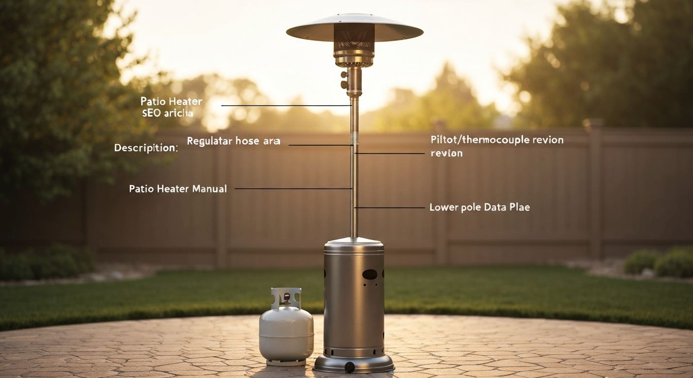
Start at the heater itself. Look for a metal data label, usually affixed to the lower pole section near the base or on the underside of the burner head housing. This label should carry the model number, serial number, BTU rating, gas type (propane/LP), and the safety certification marks (CSA or UL). Write all of this down and photograph it before you do anything else. The model number typically follows a format with letters and numbers identifying the product line and configuration.
Because Infinity Glo no longer maintains an official support presence, your best options for locating an original manual are secondary sources. Search the exact model number on Manuals.plus, ManualsLib, and the Internet Archive (archive.org). Try search strings like your model number followed by 'owner manual PDF' or 'assembly instructions'. Auction catalog listings from sites like AuctionZip and Murphy Auction occasionally include photos of heater units with enough visible detail to confirm model variants. If you find a PDF from a third-party hosting site, cross-check its contents against the BTU rating and fitting configuration on your data label before following any instructions, since manuals from similar-era heaters sometimes get mislabeled online. You can also search specifically for a quartz glass tube patio heater instruction manual to find similar assembly, safety, and troubleshooting guidance from contemporaneous models.
Infinity Glo heaters from the early-to-mid 2000s are mechanically very similar to other freestanding mushroom-style propane patio heaters of that era (Hiland, Hampton Bay, early Mainstays designs). If you cannot locate the original Infinity Glo manual, a manual from a contemporaneous Hiland or comparable heater will cover assembly, gas connections, and thermocouple procedures accurately enough to be useful, provided the BTU ratings and regulator type match. Compare the physical components before following any non-OEM manual.
Safety pre-checks before you start anything
This is not a section to skim. Propane is heavier than air, collects at floor level, and can ignite from a spark or static discharge. Before performing any inspection, repair, or assembly step involving the gas circuit, complete every check below in order.
- Confirm the propane cylinder valve is fully closed (turn clockwise until it stops). Do not assume it is closed; check it manually.
- Disconnect the regulator hose from the cylinder by unscrewing the POL or QCC fitting. Keep the disconnected end capped or pointed away from ignition sources.
- Move the heater to a well-ventilated outdoor area, away from overhanging structures, open flames, and enclosed spaces. Never perform leak tests or gas work indoors.
- Inspect the regulator hose for cracks, kinks, abrasion, or brittleness. A hose that is more than 5 years old or shows any visible damage must be replaced before use. Do not proceed with a damaged hose.
- Locate the tilt (anti-tip) switch. On most freestanding mushroom-style heaters, it is mounted near the base of the pole inside the lower housing or at the base plate. It is a small mechanical pendulum or ball-and-seat switch wired into the gas valve circuit. Know where it is before you move the unit.
- Perform a soapy-water bubble leak test every time you reconnect gas fittings (full procedure in the operating section below).
- Never use an open flame to check for gas leaks. This is an absolute rule.
- Keep a dry-chemical fire extinguisher rated for Class B fires accessible during any gas work.
- Wear safety glasses when working around gas fittings under pressure.
If you smell gas strongly at any point, do not attempt to find the source yourself. Leave the area immediately, do not operate any electrical switches or devices, close the cylinder valve if you can do so safely without entering the gas-affected area, and call 911 or your gas supplier. This instruction comes directly from Propane Education and Research Council (PERC) guidance and is not a legal formality.
Tools, replacement parts, and workspace setup
Tools you will need
- Adjustable wrench (one medium, one large) for regulator fittings and pole section connections
- Phillips-head screwdriver (#2 and #3)
- Flat-head screwdriver (medium)
- Metric hex/Allen key set (M4, M5, M6 are typical for these heaters)
- Digital multimeter with millivolt DC setting (for thermocouple and thermopile testing)
- Soft wire brush or small brass brush (for cleaning pilot orifice and thermocouple tip)
- Dish soap and small spray bottle or brush (for leak testing)
- Flashlight or headlamp (for inspecting inside the burner head and base housing)
- Combustible gas detector/sniffer (catalytic or semiconductor type, such as TPI 725A or similar) — strongly recommended for tracing slow leaks
- Torque wrench or beam-type torque tool capable of 8–12 Nm range (optional but useful for pole flange bolts)
- Spirit level (for checking heater vertical alignment)
Replacement parts to have on hand
Because Infinity Glo no longer supplies OEM parts through a manufacturer channel, you need to source compatible parts by matching specifications rather than part numbers. The parts below are the most commonly replaced items on this class of heater. Measure or confirm specifications before ordering.
- Regulator and hose assembly (verify PSI rating — most freestanding propane heaters use a 10 PSI adjustable or fixed low-pressure regulator with a QCC1/Type 1 fitting)
- Thermocouple (standard universal K-type or J-type, typically 18-inch to 24-inch lead length; confirm thread size at valve connection, usually 7/16-inch or M8)
- Thermopile (if your model uses a millivolt main valve; match the lead length and valve connector type)
- Piezo igniter module or battery igniter module (match the electrode gap and mounting thread)
- Pilot assembly/pilot orifice (cross-reference orifice diameter in thousandths of an inch if possible)
- Tilt/anti-tip switch (match the trip angle and electrical rating; a universal replacement wired inline is acceptable if OEM is unavailable)
- Gas valve assembly (this is a last-resort replacement; confirm inlet/outlet threading and pressure class before ordering)
- Burner head orifice (confirm BTU input rating and orifice size)
- Reflector/emitter dome (cosmetic/functional; match diameter)
Workspace setup
Work outdoors on a flat, hard surface (concrete or pavers, not grass). Lay down a tarp or old blanket to organize parts and avoid losing small fasteners. Have a parts tray or muffin tin for keeping screws and washers sorted by assembly stage. Keep the propane cylinder at least 10 feet away from the work area while performing any disassembly or repair. Turn off and secure all ignition sources in the area.
Unboxing and inventory checklist
If you have acquired a new-old-stock or lightly used Infinity Glo heater still in its original packaging, go through this inventory before touching the gas system. Lay out every component on a clean surface and check each item against this list. Missing or damaged parts, especially on the gas circuit, must be resolved before assembly.
- Pole sections (typically 3 sections: upper, middle, lower) — check for dents, thread damage, or corrosion at connection points
- Base/foot assembly with leveling feet or casters — check that all leveling pads are present and threads are intact
- Burner head assembly (mushroom top with emitter and reflector dome) — check emitter screen for tears or rust
- Control valve housing/knob assembly — check knob turns freely and the knob markings (OFF, PILOT, LOW, HIGH) are legible
- Regulator and hose assembly — inspect the entire hose length for surface cracking; confirm the QCC1 fitting threads are undamaged
- Pilot assembly with thermocouple lead
- Igniter (piezo button or battery igniter wired to electrode)
- Tilt switch and connecting wires (confirm the switch body and wires show no damage)
- Hardware kit: typically includes M6 and M8 bolts, cap nuts, washers, and screws (count and verify against any included parts sheet)
- Owner's manual or quick-start sheet (retain for reference even if incomplete)
Do not attempt to fire the heater if any component of the gas circuit (hose, regulator, valve, pilot assembly, or fittings) shows corrosion, physical damage, or is missing. A used heater acquired through auction or secondary market should have every gas-circuit component inspected critically, and a new regulator-and-hose assembly is a worthwhile investment before first use of any used propane heater.
Step-by-step assembly and initial setup
The assembly sequence below follows the standard approach for pedestal mushroom-style propane patio heaters. If you have partial assembly notes from any surviving paperwork, follow those for model-specific torque values. Where no values are specified, use the guidance here as a safe baseline.
- Assemble the base first. Attach the leg/foot sections to the base casting using the supplied M8 bolts and washers. Snug the bolts firmly (approximately 10–12 Nm if using a torque wrench) but do not overtighten cast components. Install leveling feet or casters if applicable.
- Stand the lower pole section upright in the base collar and secure with the base locking bolt or set screw. Check that the pole seats fully into the base socket.
- Thread the middle pole section onto the lower section. Most heaters use a left-hand or right-hand threaded collar with a locking ring — tighten the ring firmly by hand, then snug with a wrench (do not use pipe wrenches that can crush the pole).
- Route the tilt switch wiring up through the pole before attaching the upper section. The tilt switch is typically located inside or at the base; its electrical lead runs up through the pole to connect to the gas valve. Confirm the lead has enough slack.
- Attach the upper pole section and the valve/control housing. Feed gas tubing (the internal flexible tube that connects the regulator at the base to the valve at the top) through the pole assembly as you join sections. Many heaters pre-route this tubing; if yours is separate, route it before the upper section is locked in place.
- Mount the burner head onto the upper pole. This typically uses 3–4 M6 bolts through a flange. Tighten bolts in a cross pattern to seat the flange evenly; snug to approximately 6–8 Nm.
- Attach the reflector dome. Most designs use 3–4 self-tapping screws or small M6 bolts around the perimeter of the dome bracket. Tighten evenly until the dome sits flat and level.
- Connect the emitter screen/guard if separate. Confirm it seats securely and cannot be easily dislodged.
- Connect the regulator hose to the base inlet fitting. Thread the fitting clockwise (standard right-hand thread on most QCC1 connections) and tighten with a wrench — firm and snug, not gorilla tight. Overtightening brass fittings cracks them.
- Check the heater for vertical alignment using a spirit level against the pole. Adjust the leveling feet until the pole is plumb in both axes.
- Before connecting the cylinder, complete the full safety pre-check list from the earlier section.
Controls, pilot, and safety features, what you are looking at
Getting familiar with every control and safety component before you try to light the heater will save you a lot of frustration and help you diagnose faults accurately when they happen.
Control knob
The main control knob is typically a push-and-turn rotary valve with four positions: OFF, PILOT, LOW, and HIGH (sometimes labeled with symbols rather than text). You must push the knob inward (against a spring) while turning it to reach the PILOT position. This push-down action opens a small bypass circuit that supplies gas only to the pilot burner. Releasing the knob while in PILOT allows the valve to close unless the thermocouple is generating sufficient millivoltage to hold it open, that is the interlock that keeps you from flooding an unlit burner with gas.
Pilot burner and igniter electrode
The pilot burner is a small brass or stainless fitting positioned inside the burner head, aimed at the base of the main burner ring. The thermocouple tip and the igniter electrode are both positioned within a few millimeters of the pilot flame. The igniter electrode connects to the piezo sparker button (or battery-powered electronic igniter module) via a shielded wire. When you press the igniter button, you should see or hear a sharp click and a visible spark at the electrode tip. If you do not get a spark, that is the first diagnostic point for ignition failure.
Thermocouple
The thermocouple is a safety sensor: a dissimilar-metal junction that generates a small DC voltage (millivolts) when heated by the pilot flame. That voltage holds a spring-loaded safety seat in the gas valve open, allowing gas flow to continue. If the pilot goes out, the thermocouple cools, voltage drops to zero, and the valve snaps shut, stopping gas flow. This is the core safety interlock on virtually every propane patio heater of this type, including the Infinity Glo. The thermocouple tip is the small probe positioned directly in the pilot flame; the lead wire runs down to a threaded connection on the gas valve body.
Tilt (anti-tip) switch
The tilt switch is a mechanical safety device wired in series with the gas valve control circuit. If the heater tips over beyond a threshold angle (commonly 45 to 60 degrees from vertical), the switch opens and cuts power/signal to the valve, shutting off gas flow. On most freestanding heaters this switch is located inside the base housing or near the bottom of the pole. It is not something you will interact with during normal operation, but it is the first thing to check if the heater shuts off unexpectedly or refuses to stay lit when positioned on a slightly uneven surface. Never bypass this switch.
How to light the heater, adjust heat, and shut it down safely
- Confirm the cylinder valve is open (turn counterclockwise one full turn from fully closed). Do not open it all the way — one turn gives adequate flow and makes it faster to close in an emergency.
- Wait 5 minutes after connecting a fresh cylinder before attempting to light, to allow any residual air in the line to clear.
- Rotate the control knob to the PILOT position (push inward and turn). Keep the knob pushed in.
- Press the piezo igniter button (or trigger the battery igniter) repeatedly while holding the knob in. You should see the pilot flame ignite within 3–5 button presses. If it does not light in 10 attempts, turn the knob back to OFF, wait 5 minutes for gas to clear, and try again.
- Once the pilot is lit, continue holding the knob in for 30 to 60 seconds to allow the thermocouple to heat up and generate sufficient voltage to hold the valve open. This is the most common cause of frustration: releasing the knob too early drops the pilot.
- Slowly release the knob. If the pilot stays lit, the thermocouple is working. If it goes out, the thermocouple is not generating enough voltage (see the troubleshooting section below).
- With the pilot lit and the knob released, turn the knob to LOW. You should hear and see the main burner ignite from the pilot flame. Allow 2–3 minutes at LOW before advancing to HIGH.
- Adjust heat output by rotating the knob between LOW and HIGH. The heater is certified under CSA/ANSI Z83.26-20 standards for outdoor use; do not use it indoors or in enclosed spaces regardless of perceived ventilation.
- To shut down: rotate the knob back through LOW to PILOT, then to OFF. Close the cylinder valve by turning it fully clockwise. Never leave the cylinder valve open when the heater is unattended or stored.
Soapy-water leak test, do this every time you reconnect gas
Mix a thick solution of dish soap and water in a spray bottle or small cup. With the cylinder valve open and the heater in the OFF position (gas is pressurized but not flowing to the burner), apply the soapy solution to every fitting: the cylinder valve connection, the regulator body, the hose fittings at both ends, and the inlet fitting at the base of the heater. Watch for 30 seconds. Growing bubbles indicate a leak. If you see bubbles anywhere: turn the cylinder valve off immediately, do not attempt to light the heater, tighten or replace the leaking fitting, and retest before proceeding. A combustible gas detector/sniffer used alongside the soap test will catch slow leaks the soap test might miss at low flow rates.
Troubleshooting common faults
Heater won't light at all (no spark or no pilot ignition)
Work through this in order. First, confirm gas is actually reaching the pilot by holding the knob in PILOT position and looking for any smell of propane at the burner head (a faint smell confirms gas flow; no smell suggests a blockage or closed valve). Then check the spark:
- With the cylinder closed and no gas flowing, press the igniter button and watch for a spark at the electrode tip inside the burner head. Use a flashlight.
- No spark: check the electrode wire connection at both ends (electrode and igniter module). Corrosion or a loose push-on connector is common. Clean with fine sandpaper or emery cloth.
- Still no spark: test the piezo unit by disconnecting the electrode wire and holding the wire end 3–4 mm from a metal ground (pole section) while pressing the igniter. Spark appears here but not at the electrode means the electrode wire is broken or the electrode tip is cracked. Replace the electrode.
- No spark even from the disconnected wire test: the piezo/battery module is faulty. Replace it. These are inexpensive universal parts available from patio heater parts suppliers and online retailers.
- Spark is present but pilot won't light: confirm the pilot orifice is not blocked. Remove the pilot assembly (with gas off and cylinder disconnected), and use a thin strand of wire or compressed air to clear the orifice. Do not enlarge the orifice with a drill bit.
- Check electrode gap. The tip of the electrode should be approximately 3–5 mm from the pilot burner body. Gently bend the electrode back into position if it has shifted.
Pilot lights but won't stay lit (drops out when you release the knob)
This is almost always the thermocouple. See MHSC / Fireplace manual, Thermocouple/thermopile millivolt diagnostic values and test procedure (example OEM manual) for typical millivolt thresholds used by manufacturers See MHSC / Fireplace manual — Thermocouple/thermopile millivolt diagnostic values and test procedure (example OEM manual) for typical millivolt thresholds used by manufacturers.. Here is how to diagnose it precisely:
- With the pilot burning and the knob held in, set your multimeter to DC millivolts. Disconnect the thermocouple lead at the gas valve terminal (small threaded nut, typically 7/16-inch). Touch the meter probes to the thermocouple lead and its body/ground.
- A healthy thermocouple generates more than 10–15 mV while held in a stable pilot flame. Reading below 10 mV means the thermocouple is not producing enough voltage to hold the valve open.
- Before replacing the thermocouple, check the pilot flame position. The flame tip should be impinging directly on the thermocouple probe (the small metal rod, not the lead wire). If the flame is blowing sideways or barely touching the probe, it will not heat the junction adequately. Clean the pilot orifice and check that the burner assembly is seated correctly.
- If the millivolt reading is below threshold and the flame position is correct, replace the thermocouple. It is a standard universal part. Match the thread size on the valve connection (most are 7/16-inch or M8 x 1.0) and ensure the new probe is long enough to position correctly in the flame.
- After replacement, retest: light the pilot, hold for 45 seconds, and check millivolt reading before releasing the knob.
Main burner won't light or cuts out shortly after ignition
- Confirm the pilot is fully stable and burning correctly before suspecting the main burner circuit.
- With the pilot lit and knob turned to LOW, listen and watch for the main burner ignition. A healthy burner ignites within 3–5 seconds of reaching LOW position.
- No main burner: check that the burner orifice is not blocked. Turn off gas, disconnect cylinder, and inspect the main orifice for debris or spider webs (spiders are a real and common problem in stored heaters). Clear with compressed air.
- Main burner lights then cuts out: this can be a thermopile issue (if your model uses a millivolt-powered main valve). Test with multimeter at DC millivolts. A functioning thermopile should generate 250–300 mV minimum when the pilot has been running for 2–3 minutes. Below this range, replace the thermopile.
- Main burner cuts out and tilt switch is suspected: gently verify the heater is perfectly level. Even a slight lean on soft ground can trip the tilt switch. Check the switch wiring for loose connections.
Tilt switch trips or causes unexpected shutoff
- Place the heater on a confirmed level, hard surface. If it shuts off immediately on level ground, the tilt switch itself may be faulty.
- Locate the tilt switch (typically inside the base housing). With the heater off and cylinder disconnected, trace the two wires from the tilt switch. Use a multimeter set to continuity or resistance: with the heater upright and level, the switch should show continuity (closed circuit). Tilting it beyond its threshold should open the circuit.
- If the switch shows open circuit when the heater is perfectly level, the switch is defective. Replace it with a matching universal tilt switch (match the voltage/amperage rating and approximate trip angle). Do not bypass the switch with a wire jumper. This defeats a critical safety feature and creates a fire hazard.
- Test the replacement: with the heater assembled and running, gently tilt the unit by 45–60 degrees. The heater must shut off. If it does not, the replacement switch is also faulty or incorrectly wired.
Common faults at a glance
| Symptom | Most Likely Cause | DIY Fix |
|---|---|---|
| No spark when igniter pressed | Failed piezo module or broken electrode wire | Clean connections; replace electrode or piezo unit |
| Pilot lights, drops when knob released | Thermocouple below threshold (under 10–15 mV) | Clean probe and check flame position; replace thermocouple |
| Pilot won't light (spark present) | Blocked pilot orifice or wrong electrode gap | Clear orifice with wire; adjust electrode gap to 3–5 mm |
| Main burner won't ignite | Blocked main orifice or weak thermopile | Clear orifice; test thermopile mV; replace if under 250 mV |
| Heater shuts off intermittently | Faulty or tripped tilt switch | Level the heater; test switch continuity; replace switch |
| Gas smell with no flame | Hose or fitting leak | Perform bubble test; tighten or replace leaking component |
| Pilot flame very weak or yellow | Dirty pilot orifice or low gas pressure | Clean orifice; check regulator output pressure |
Parts identification, diagrams, and ordering
Since Infinity Glo does not publish a current parts catalog, you need to work from what you have. If the heater came with any paperwork, look for an exploded-view diagram, which shows every component with a reference number and sometimes a part number. Photograph every component of your heater: the gas valve body (look for any cast markings), the thermocouple thread and lead length, the pilot orifice size if visible, and the regulator label. These details let you cross-reference compatible parts from current suppliers.
For cross-referencing, Hiland (now sold under various brands) and Hampton Bay patio heater parts catalogs are publicly available and cover the same category of freestanding mushroom heater. See the Hiland BURN‑2400 owner’s manual, Hardware contents, replacement parts list (example OEM parts list) for a typical parts list that includes regulator and hose assembly, pilot orifice/pilot assembly, thermocouple, thermopile, piezo/electronic igniter module, tilt switch, gas valve assembly, reflector/emitter element, burner orifices, and mounting hardware blank" rel="noopener noreferrer">Hiland BURN‑2400 owner’s manual — Hardware contents, replacement parts list (example OEM parts list). Search Manuals.plus or ManualsLib for 'patio heater parts list' along with your BTU rating (40,000 BTU is common for full-size freestanding units). If you also own a Thermo Tiki heater, search for the thermo tiki outdoor propane patio heater manual as a cross-reference, many assembly and safety details are similar and can help when Infinity Glo documentation is unavailable. The hardware fasteners used in these heaters are standard metric: M6x10, M6x22, and M8x16 bolts appear in most OEM hardware kits, so replacement hardware from any hardware store is straightforward.
Order gas-circuit parts (thermocouples, thermopiles, gas valves, pilot assemblies) only from established patio heater parts retailers or HVAC supply houses. Avoid uncertified generic parts for safety-critical components. Confirm that any replacement thermocouple or thermopile is rated for propane (LP) service and matches the connection thread and lead length of the original.
Maintenance schedule and routine care
Before each use
- Visually inspect the hose and regulator for damage
- Check all pole connections for tightness
- Confirm the tilt switch has not been bumped or damaged during storage
- Perform a bubble leak test after reconnecting the cylinder
Every season (or every 50 hours of use)
- Clean the pilot orifice and thermocouple probe tip with a soft brass brush
- Inspect the igniter electrode for carbon buildup; clean with fine emery cloth or replace
- Check all gas-circuit connections with a bubble test
- Inspect the emitter screen for rust, holes, or debris accumulation
- Wipe down the reflector dome with a mild cleaner; inspect for corrosion
- Inspect the regulator hose for age-related cracking; replace if over 5 years old or if any cracking is visible
- Operate the tilt switch test (tilt the heater while running to confirm shutoff)
Winterizing and storage
- Turn off and disconnect the propane cylinder. Store the cylinder outdoors in an upright position in a well-ventilated area, away from living spaces. Do not store propane cylinders indoors, in garages, or in sheds with limited ventilation — this is a requirement under NFPA 58.
- Cap the regulator inlet fitting to keep insects and moisture out during storage.
- Clean the entire burner head assembly. Spider webs and debris in the burner tube or orifice are among the most common causes of ignition failure on first use after winter storage.
- Apply a thin coat of food-grade or appliance-safe oil to metal surfaces prone to rust (pole sections, base hardware).
- Cover the heater with a breathable heater cover — not a non-breathable plastic tarp, which traps moisture and accelerates corrosion.
- If storing in a garage or shed (without the cylinder), ensure the space is not adjacent to ignition sources and is well-ventilated.
- Before bringing the heater out of storage in spring, perform the full pre-use safety checklist and a bubble leak test.
When to stop and call a licensed technician
There are specific situations where DIY is not appropriate and calling a licensed LP gas technician or plumber is the right call. Gas appliance repair has a clear line between what a competent homeowner can safely do and what requires a licensed professional. Here is where that line falls for an Infinity Glo heater:
- Any repair involving the internal gas valve mechanism. External replacement (swap the entire valve) is acceptable DIY. Disassembling and re-assembling a gas valve is not.
- Any conversion from propane to natural gas or vice versa. This requires orifice sizing, regulator matching, and compliance with ANSI Z223.1/NFPA 54. It must be performed by a licensed gas fitter in your jurisdiction.
- Connecting the heater to a permanent piped natural gas supply. This is a licensed plumber/gas fitter job, full stop.
- If a leak cannot be found or eliminated after replacing the hose and retesting all fittings, stop using the heater and have it inspected by a qualified technician.
- If the gas valve will not close fully and gas continues to flow with the knob in the OFF position, do not use the heater. Disconnect the cylinder and have the valve replaced or inspected by a professional.
- If the heater has been knocked over while lit and you are unsure whether any internal damage has occurred, have it inspected before relighting.
The standards governing these heaters (CSA/ANSI Z83.26-20 and NFPA 58) exist precisely because propane failures can escalate quickly. Being honest about the limits of DIY repair is not being overly cautious. It is just accurate.
Comparing Infinity Glo to similar heaters you might encounter
Because Infinity Glo is a discontinued brand, many owners end up comparing it to current or other legacy heaters when deciding whether to repair or replace. The heaters below are in the same category (freestanding or tabletop propane, mushroom or infrared style) and have their own manual resources if you need cross-reference material. The Thermo Tiki outdoor propane patio heater and the Bali Outdoors portable patio heater both used similar freestanding designs with comparable gas valve and thermocouple configurations. The Belleze patio heater and the tall Mainstays patio heater are also directly comparable in terms of parts and troubleshooting logic. You can also consult the tall mocha mainstays patio heater manual for directly comparable assembly, parts, and troubleshooting information. For model-specific details and a closely matching parts and assembly reference, see the Belleze patio heater manual. For tabletop designs, the Cuisinart tabletop patio heater and the quartz glass tube patio heater use different burner configurations but share the same thermocouple and tilt-switch principles. The Sunbeam Patio Master follows a comparable millivolt gas valve layout. For cross-reference on the millivolt gas valve layout, see the Sunbeam Patio Master manual.
| Heater / Brand | Style | Manual Availability | Parts Support |
|---|---|---|---|
| Infinity Glo | Freestanding mushroom, propane | Discontinued; no OEM source | Cross-reference only |
| Thermo Tiki | Freestanding mushroom, propane | Available online | Limited aftermarket |
| Bali Outdoors Portable | Freestanding, propane | Available online | Some OEM available |
| Belleze | Freestanding mushroom, propane | Available from retailer | Aftermarket compatible |
| Mainstays (Tall Mocha) | Freestanding mushroom, propane | Available from retailer | Aftermarket compatible |
| Cuisinart Tabletop | Tabletop, propane | Available from Cuisinart | OEM available |
| Sunbeam Patio Master | Freestanding, propane | Available online | Limited aftermarket |
| Quartz Glass Tube | Tabletop/freestanding, propane | Varies by brand | Universal parts common |
If your Infinity Glo has severe corrosion on the pole sections, a cracked emitter, or a gas valve that cannot be sourced, the honest repair-versus-replace calculation usually tips toward replacing with a current heater that has active parts support. But if the core gas circuit is sound and the issue is a thermocouple, igniter, or tilt switch, repair makes complete sense, these are inexpensive universal parts and the heater is mechanically simple.
FAQ
What official sources and documentation should I locate to create a complete Infinity Glo patio heater manual and troubleshooting guide?
Locate the original OEM owner/installation/parts manuals and exploded‑view parts lists (manufacturer or authorised distributor). If no active Infinity Glo website exists, check: archived product PDFs, auction/used listing photos, retailer product pages, library/manual‑aggregator sites (Manuals.plus, ManualsLib), and trademark/registration records to confirm brand history. Collect applicable standards and code references (CSA/ANSI Z83.26‑20 • CSA 2.37‑20, ANSI Z21.97, ASTM F2644, NFPA 58, ANSI Z223.1/NFPA 54) and reputable safety guidance (Propane Education & Research Council). Record model numbers/label photos (serial plate) and capture part numbers from any found parts diagrams. If OEM documents cannot be obtained, clearly note gaps and use conservative general‑industry procedures only (no guesswork about proprietary internals).
What model identification information do I need and how should I advise readers to find it?
Require photos/details of the heater’s data/serial plate: model number, serial number, BTU rating, gas type (LP or NG), and CSA/ANSI or other certification marks. Advise readers to: 1) inspect the base/near the regulator/burner area for a metal plate or sticker, 2) take clear photos for online searches or parts requests, 3) compare visible features (reflector shape, burner head, control knob cluster, pilot position) with available OEM or third‑party manual images to narrow variants, and 4) record regulator type (pigtail, QCC/OPD connection) and valve brand if visible. Document all identification steps in the manual so users can match their unit to the correct instructions/parts list.
Which safety standards and codes must be cited or followed in the manual?
Cite and summarize: CSA/ANSI Z83.26‑20 • CSA 2.37‑20 (gas‑fired outdoor infrared patio heaters) or ANSI Z21.97 (outdoor decorative gas appliances), ASTM F2644 (performance testing), NFPA 58 (LPG Code), and ANSI Z223.1 / NFPA 54 (National Fuel Gas Code). Also reference PERC guidance for cylinder handling and leak response. Use these standards to inform labeling, clearance distances, installation restrictions, and the requirement that permanent gas‑line work or conversions be done by licensed technicians and in compliance with local code.
What pre‑check safety steps should the manual require before assembly, operation, or repair?
Require users to: 1) work outdoors or in well‑ventilated outdoor locations and keep fuel cylinders outdoors/upright; 2) ensure cylinder valve closed and regulator pressure relieved before disassembly; 3) perform a visual inspection for rust, corrosion, dents, cracked hoses, or insect nests in pilot/burner; 4) identify and locate the tilt/anti‑tilt switch and main gas shutoff; 5) have a 2A:10B:C or larger rated fire extinguisher nearby; 6) use only soapy‑water or an approved gas‑sniffer for leak checks (never use open flame); 7) wear eye protection and gloves; and 8) stop and call a licensed gas technician for any suspected regulator or gas‑line leak they cannot isolate or fix safely.
What tools, fasteners, and parts list should be included for assembly and common repairs?
Provide a tools checklist: adjustable wrench (1/2"–1"), set of metric/imperial sockets and wrenches (M6, M8 sizes), Phillips and flat screwdrivers, needle‑nose pliers, multimeter (mV range), soapy‑water spray bottle, combustible‑gas detector (optional), small wire brush, fine sandpaper, and torch‑safe cleaning tools. Common hardware list: M6 and M8 bolts/nuts/washers and self‑tapping screws typical of patio heaters. Common replacement parts to identify: regulator & hose assembly, QCC/OPD valve, pilot burner and pilot orifice, thermocouple, thermopile (if equipped), piezo/electronic igniter module, tilt switch/microswitch, gas control valve assembly, burner head/orifices, reflector/emitter element, mounting fasteners. Include part‑ordering tips: photo of part, OEM part number if available, heater model/serial, dimensions of fittings, and preferred vendors (OEM, authorised dealers, parts marketplaces).
What step‑by‑step assembly and setup instructions should be provided?
Outline sequenced assembly: 1) inventory parts and fasteners using provided hardware list; 2) assemble base/pedestal per exploded view, torque M8/M6 fasteners hand‑tight then specified torque if provided; 3) mount burner head and reflector securely; 4) install regulator/hose assembly following connection orientation and thread type—use approved LP regulator for propane, ensure OPD/QCC connections; 5) make final mechanical checks: level the base, ensure tilt‑switch accessible and not compressed, tighten reflector screws; 6) perform initial leak test (soapy‑water) at cylinder/regulator, hose, and connections with valve slowly opened; 7) light pilot per lighting procedure (push/turn to PILOT while pressing piezo or battery igniter). State to stop immediately if leaks detected and close cylinder valve.