
The Westinghouse 1500W freestanding electric patio heater (model WES31-15110, also sold under Paramount branding) is a straightforward 120 V / 1500 W infrared heater that you can fully assemble, troubleshoot, and repair yourself with a basic tool kit and a digital multimeter. The official 9-page owner's manual (WES31-15110BLK) covers assembly, grounding, clearances, and a 1-year limited warranty. This guide expands on that manual with complete step-by-step procedures for every common fault, multimeter test values, parts references, and maintenance schedules so you can keep the heater running for its full rated life without an unnecessary service call.
Westinghouse 1500W Freestanding Electric Patio Heater Manual

Grant Mercer
5 Aug 2026
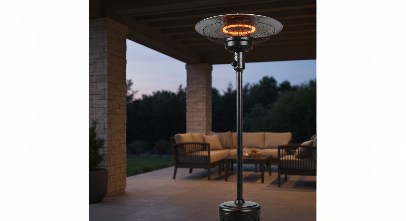
What this guide covers and which models it applies to
This article is written specifically for the Westinghouse WES31-15110 (and its black-finish variant WES31-15110BLK), a 1500 W carbon-coil infrared heater rated IP24 and listed to ANSI/UL 1278 for movable electric room heaters. If you have a Paramount-branded unit with the same form factor and 1500 W / 120 V rating, the internals, wiring, and repair procedures are identical. The companion articles on the Westinghouse 1500W freestanding patio heater manual and the broader Westinghouse electric patio heater manual go deeper on variant-specific wiring diagrams if your label shows a different model suffix.
This guide is for homeowners, renters, and DIYers who are comfortable using hand tools and a multimeter. You do not need HVAC training. You do need to follow every unplug-first instruction without shortcuts. If at any point you find burned wiring, a cracked element tube, or a failed ground conductor, stop and escalate. Those situations are covered in the 'When to stop DIY' section near the end.
Quick-start summary and printable safety checklist
Before you do anything else, run through this checklist. Print it out and physically tick each box before first use, after storage, and before any repair session.
- Unplug the heater from the wall outlet before any assembly, servicing, or inspection inside the unit.
- Confirm the wall outlet is a grounded 3-prong 120 V / 15 A (or 20 A) circuit.
- Check the power cord for cuts, kinks, melted insulation, or a bent plug. Do not use the heater if any damage is present.
- Verify the heater is standing on a flat, stable, non-combustible surface before plugging in.
- Confirm overhead clearance: at least 1 ft 6 in (50 cm) above the heater head.
- Confirm side clearances: at least 9 in (25 cm) on all sides.
- Confirm floor clearance: keep combustibles at least 5 ft (1.8 m) below the element.
- Test the tip-over switch by gently tilting the unit past 30 degrees. The heater should cut power immediately.
- If using an extension cord, confirm it is at minimum 14 AWG and rated for at least 1875 W.
- Verify the remote control (if fitted) has fresh batteries and the receiver LED responds.
- Read any local code requirements or landlord rules for outdoor electric heaters before installation.
Where to find the official manual
The authoritative source is the Westinghouse product page for the WES31-15110BLK, where a direct PDF download link is listed under the product's documentation section. See the Westinghouse WES31-15110 1500W freestanding patio heater manual (WES31-15110BLK) for the full owner’s manual and detailed specifications westinghouse wes31 15110 1500w freestanding patio heater manual. Type your full model number (WES31-15110BLK) into the search bar on westinghouselighting.com or the main Westinghouse product site. The manual PDF is 9 pages and covers assembly, grounding, specifications, cleaning, and warranty contact information. For the official PDF, see the westinghouse electric patio heater manual.
If the manufacturer page is temporarily unavailable, major retailers (Lowe's, The Home Depot, Target, Tractor Supply, Costco) all host the same product listing for the WES31-15110BLK and some link directly to the same PDF. Search the retailer's site for the model number and look for a 'Documents' or 'Manuals & Guides' tab on the product page. The Paramount-branded variant of this heater also ships with a near-identical manual. If yours is branded Paramount, check the Paramount patio heater manual resource on this site for any label-specific differences before downloading the Westinghouse PDF.
For warranty service or to request a replacement printed manual, call Westinghouse customer support at 1-866-967-7333, extension 227. Have your model number and purchase date ready before you call.
Reading the model and serial label
The rating label on the WES31-15110 is typically located on the underside of the heater head or on the back of the main pole near the base. Here is what each line means and why it matters for diagnostics and parts ordering.
| Label field | Example value | Why it matters |
|---|---|---|
| Model No. | WES31-15110BLK | Use the full string (including color suffix) when ordering parts or downloading the exact manual version. |
| Serial No. | Alphanumeric string | Required by Westinghouse customer service for warranty claims and to confirm production batch. |
| Rated Voltage | 120 V ~ | Confirms AC mains supply. Do not use on 240 V circuits. |
| Rated Frequency | 60 Hz | U.S. standard; confirms the unit is not a 50 Hz import variant. |
| Rated Power | 1500 W | The design wattage. Used to calculate expected current (12.5 A) and cold element resistance (~9.6 Ω). |
| IP Rating | IP24 | Splash-proof on two sides. Acceptable for covered outdoor use; not submersible. |
| Safety listing | ETL or UL mark | Confirms testing to ANSI/UL 1278. If this mark is missing or damaged, escalate before use. |
Photograph the label with your phone before you do anything else. The serial number wears off quickly, and you will need it if you ever call for parts or warranty service.
Safety warnings and PPE before any work
Electric heaters carry real shock and burn hazards. The WES31-15110 runs at 120 V and draws up to 12.5 A during normal operation. The heating element tube gets hot enough to cause serious burns within seconds. Observe these rules on every single session, not just the first one.
- Always unplug before opening any cover, removing any fastener, or touching any internal component. Do not rely on the power switch alone.
- Wait at least 10 minutes after unplugging before touching the element tube or the guard ring. The carbon coil retains heat.
- Wear insulated gloves when handling the element assembly and safety glasses when removing fasteners.
- Do not modify, extend, or re-terminate the power cord. The manufacturer's manual explicitly prohibits cord modification. If the cord is damaged, replace the entire cord assembly with an OEM part.
- If you doubt whether your outlet is properly grounded, check with a qualified electrician before plugging in. The manual is direct about this.
- Never operate the heater under a standard indoor ceiling or in an enclosed space without adequate ventilation.
- This heater is electric only. All gas patio heater procedures are completely different and do not apply here.
Tools, test equipment, and replacement-part specs
You do not need specialized tools. Here is a complete list of what to have on the bench before you start any repair or assembly session.
| Item | Specification / setting | Used for |
|---|---|---|
| Allen (hex) key | Included in the kit; matches M6 and M4 fasteners | Assembling base and pole |
| Phillips-head screwdriver | No. 2 | Accessing heater head cover, control board, and cord clamp |
| Flathead screwdriver | Small, 3 mm tip | Releasing wire connectors and removing the cord holding plate |
| Digital multimeter (DMM) | Resistance (Ω) range: 0–200 Ω; continuity mode; AC voltage to 200 V | Testing element, tilt switch, thermal cutout, and outlet voltage |
| Needle-nose pliers | Standard 6 in | Removing and reinstalling wire connectors |
| Torque note | Snug hand-tight plus 1/4 turn for M6 screws; do not over-torque aluminum threads | Base and pole fasteners |
| Replacement heating element | 1500 W carbon coil, fits WES31-15110; order from Westinghouse parts portal or contact 1-866-967-7333 ext 227 | Element replacement |
| Replacement thermal cutout | OEM spec; confirm temperature rating from Westinghouse parts portal | Overheat protection replacement |
| Replacement tilt switch | OEM spec; normally-closed ball-type switch | Tip-over protection replacement |
| AA or AAA batteries | Per remote label | Remote control |
Set your multimeter to resistance mode before touching any component. Fluke's guidance (and good general practice) is to zero the leads by touching them together and pressing the REL button to subtract lead resistance before measuring low-ohm components like heating elements. This keeps your readings accurate in the single-digit ohm range where the element lives.
Step-by-step assembly
Unpacking and parts inventory
Lay everything out on a clean flat surface before you start. The shipped kit for the WES31-15110BLK contains the following. Check each item off before proceeding.
- Heater head assembly (element, guard, and control panel pre-installed)
- Main vertical pole
- Base assembly
- 1x Allen key
- 2x M6 x 50 mm screws (for base attachment)
- 2x M4 x 35 mm screws (for pole/head joint)
- 2x round washers
- 1x cord holding plate
If any hardware is missing, contact the retailer for a replacement fastener kit before proceeding. Do not substitute hardware store screws: the thread pitch and shear rating are specific to the aluminum casting.
Assembling the base, pole, and heater head
- Invert the heater head and pole assembly onto a padded surface so the base attachment point is facing up. This protects the guard ring and element tube.
- Feed the power cord from the heater head down through the hollow center of the pole until it exits at the base end.
- Align the base casting with the bottom of the pole. Insert the two M6 x 50 mm screws through the base holes and thread them into the pole, adding the round washers under each screw head.
- Tighten the M6 screws with the included Allen key. Snug hand-tight, then an additional quarter turn. Do not exceed this; the casting is aluminum.
- Route the cord out through the cord exit slot in the base. Clip the cord holding plate over the cord at the base exit point and fasten it with the M4 x 35 mm screws to relieve strain on the internal connections.
- Stand the unit upright. Verify the heater head is level and does not wobble. If it rocks, check that all four base feet are making contact with the floor.
- Do not plug in yet. Complete the installation and placement checks in the next section first.
Installation and placement checks
Where you put this heater matters as much as how you wire it. The WES31-15110 is IP24 rated, which means it tolerates splash from two directions but is not designed for direct rain exposure. A covered patio or pergola is the correct environment. Direct exposure to rain voids the warranty and creates a shock hazard.
| Clearance direction | Minimum distance (from manual) | What to measure against |
|---|---|---|
| Above heater head | 1 ft 6 in / 50 cm | Ceiling, pergola beam, or overhead structure |
| Sides (all directions) | 9 in / 25 cm | Walls, furniture, curtains, railings |
| Below element (floor combustibles) | 5 ft / 1.8 m | Rugs, wood decking, stored items |
| Extension cord (if used) | Min. 14 AWG, rated ≥ 1875 W | Cord label or markings |
Always follow the exact clearance values in your copy of the manual. The table above reflects the values published in the WES31-15110BLK documentation, but Paramount-labeled variants or updated print runs may specify different figures. If your manual differs, the manual wins.
For the mounting surface, the base feet need a flat, stable, non-combustible surface: concrete, tile, or composite decking. The unit is top-heavy when the element head is extended. Do not place it on uneven pavers, grass, or carpet without confirming it cannot tip. The tip-over switch is a last-resort safety device, not a substitute for stable placement.
Route the cord along the wall or a fixed structure and secure it with cable clips to prevent a trip hazard. Never run the cord under a rug or mat. The cord is rated for continuous 12.5 A draw at outdoor temperatures; burying it under insulation raises the conductor temperature and degrades the insulation over time.
Site-setup checklist before first plug-in
- Heater is on a flat, stable, non-combustible surface.
- All three clearance dimensions (above, sides, below) are confirmed against the table above.
- Power cord is undamaged and routed without tight bends.
- Wall outlet is 120 V, 60 Hz, and grounded (3-prong).
- No extension cord in use, or extension cord is 14 AWG minimum and rated ≥ 1875 W.
- Tip-over switch test completed (tilt unit, confirm power cuts; stand unit upright, confirm power restores).
- Overhead structure is non-combustible or at or beyond minimum clearance.
- Children and pets are kept outside the 5 ft floor clearance zone during operation.
Electrical safety and pre-use checks
Before the first use of the season, or after any storage period, run these electrical checks. They take about five minutes and will catch the most common failure modes before they become a hazard.
- With the heater unplugged, set your multimeter to AC voltage (200 V range) and measure the wall outlet. You should read between 115 V and 125 V. A reading below 110 V means the circuit is overloaded or there is a wiring problem. Do not proceed until voltage is within range.
- Plug the heater in but leave it switched off. Check that the outlet breaker has not tripped.
- Switch the heater to its lowest power setting. The element should glow orange within 30 seconds and you should feel radiant heat within 60 seconds.
- While it is running, visually inspect the element tube through the guard ring. Look for any dark or black spots on the tube (cold spots indicating a partial element failure) or any visible cracks.
- After 5 minutes of operation, unplug and wait 10 minutes. Then inspect the cord where it exits the base: if it is warm to the touch at the strain relief point, the cord holding plate may be loose or the cord is undersized for the load.
Troubleshooting: symptoms, causes, and fixes
No power at all (heater completely dead)
Start at the wall, not the heater. Plug a lamp or phone charger into the same outlet. If that device also has no power, the circuit breaker has tripped or the outlet is faulty: reset the breaker or test a different outlet. If the outlet is live and the heater is still dead, check the following in order.
- Inspect the plug and cord for physical damage. A bent or corroded prong will prevent contact.
- Check whether the unit was tipped over recently. The tip-over switch may have latched in the open position. Stand the heater fully upright on a flat surface, wait 10 seconds, and try again.
- Some WES31-15110 units include an inline fuse in the cord set or near the control board. Unplug, access the fuse holder (usually a small barrel cap near the plug), and check the fuse with your multimeter on continuity mode. No continuity means a blown fuse: replace with the same amperage and voltage rating shown on the fuse body.
- If none of the above resolves the issue, proceed to the tilt switch and thermal cutout tests in the repair sections below.
Heater powers on but produces no heat
If the control panel lights up and the fan (if fitted) runs but the element does not glow, the heating element or the thermal cutout is the most likely culprit. Use the multimeter procedure in the repair section to test both. A correctly functioning 1500 W / 120 V element should read approximately 9.6 Ω cold. A completely open (infinite resistance) reading confirms a failed element. A thermal cutout that has tripped and will not reset also produces this symptom.
Heater operates intermittently or shuts off unexpectedly
Intermittent shutdown is almost always one of three things: the overheat protection tripping because clearances are too tight, a loose connection at the element terminals, or a partially failed tilt switch that is triggering on minor vibration. Check clearances first: measure the actual overhead and side distances with a tape measure and compare them to the table in the Installation section. If clearances are correct, unplug and gently wiggle all wire connectors at the element terminals. A connector that moves freely is not fully seated. Reseat it and test. If the problem persists, test the tilt switch per the procedure below.
Tip-over switch problems
The WES31-15110 uses a normally-closed ball-type tilt switch that opens the circuit when the heater exceeds a critical angle, cutting power to the element in compliance with blank" rel="noopener noreferrer">UL 1278 tip-over protection requirements. Two failure modes occur: the switch stays open after the unit is returned to upright (so the heater appears dead), or the switch develops intermittent contact and trips randomly during normal use.
- Unplug the heater.
- Access the tilt switch. On the WES31-15110 it is located inside the base assembly, near the cord entry point.
- Disconnect the switch leads and set your multimeter to continuity mode.
- With the heater standing fully upright, probe both leads of the switch. A good switch will show continuity (closed circuit) when upright.
- Slowly tilt the unit past 30 degrees. Continuity should break (open circuit) as the ball rolls off the contact.
- Return the unit to upright: continuity should restore within 2 to 3 seconds as the ball settles.
- If the switch fails any of these tests, order a replacement OEM tilt switch from the Westinghouse parts portal and swap it. The leads use push-on connectors: no soldering required.
Remote control not working
Some WES31-15110 variants include a remote control. The transmitter and receiver are factory matched. If the remote stops responding, work through these checks before assuming the receiver is failed.
- Replace the remote batteries. This is the cause of remote failure in the majority of reported cases.
- Stand within 15 feet (approximately 4.5 m) of the heater with a clear line of sight to the receiver window. Walls and metal furniture block the signal.
- Confirm the heater is switched on at the unit's physical power button. The remote cannot power up a unit that is switched off at the panel.
- If the remote still does not respond after new batteries and close-range testing, the receiver pairing may have been lost. Consult the remote/receiver documentation that shipped with your unit for the re-pairing procedure (it typically involves holding the receiver button while pressing the remote power key).
- If re-pairing fails, contact Westinghouse at 1-866-967-7333 ext 227 to order a replacement matched remote/receiver set.
Repair procedures for replaceable parts
Testing and replacing the heating element
The WES31-15110 uses a carbon coil infrared element with a rated average life of approximately 5,000 hours. Westinghouse's product page notes the carbon coil bulb's average life is about 5,000 hours and recommends contacting Westinghouse customer support to obtain replacement parts or service Westinghouse's product page notes the carbon coil bulb's average life is about 5,000 hours and recommends contacting Westinghouse customer support to obtain replacement parts or service.. This is a replaceable part. Here is how to test and replace it.
- Unplug the heater. Wait 10 minutes for the element to cool completely.
- Remove the guard ring screws (Phillips No. 2) and swing the guard open to access the element tube.
- Disconnect the two element lead wires from their push-on terminals. Note or photograph which lead goes to which terminal.
- Set your multimeter to the lowest resistance range that covers 0 to 50 Ω. Touch the probes together and press REL to zero out lead resistance.
- Place one probe on each element terminal. A good element should read approximately 9.6 Ω (derived from R = V² / P = 120² / 1500). Readings between 8 Ω and 12 Ω cold are acceptable depending on temperature. An open circuit (OL or infinite) means the element has failed and must be replaced.
- To install the replacement, reverse the removal steps. Seat the lead connectors fully until they click. Replace the guard ring and torque the screws snug.
- Plug in and test: the element should begin to glow within 30 seconds.
Testing and replacing the thermal cutout (overheat protection)
The thermal cutout is a one-shot or resettable fuse mounted close to the element. Its job is to open the circuit if the heater reaches a dangerously high temperature, typically from blocked airflow or proximity to a combustible surface. A tripped one-shot cutout will not reset and must be replaced.
- Unplug. Access the heater head interior by removing the rear cover screws.
- Locate the thermal cutout: it is a small disc or cylinder clamped against the element bracket, with two lead wires.
- Disconnect the leads and test with the multimeter on continuity mode. A good cutout shows continuity. An open cutout shows no continuity and must be replaced.
- Order the replacement cutout by model number from the Westinghouse parts portal (parts.wpowereq.com) or by calling 1-866-967-7333 ext 227. Confirm the temperature rating matches the original.
- Install the new cutout in the same orientation and clamp position. Reconnect the leads, reinstall the cover, and test.
Replacing the power cord
If the power cord shows any cuts, melted sections, or a bent plug, replace it. The manufacturer's manual explicitly states you must not modify the cord. That means OEM replacement only: same gauge, same length, same plug type. Do not attempt to splice or repair a damaged cord. Order the replacement cord assembly from Westinghouse parts and swap the entire assembly, reconnecting at the internal terminal block using the push-on connectors.
Parts reference and typical part numbers
Westinghouse does not publish a universal exploded-parts diagram in the 9-page consumer manual, but the parts portal (parts.wpowereq.com) allows you to search by model number to view available assemblies and part numbers. The WES31-15110 Westinghouse parts page lists replacement elements, cord assemblies, and remote/receiver sets. Always use the full model number including the color suffix (BLK) when searching, as electrical specs can vary by variant.
| Part | Description | Where to order |
|---|---|---|
| Heating element | 1500 W carbon coil infrared tube, WES31-15110 spec | Westinghouse parts portal (parts.wpowereq.com) or call 1-866-967-7333 ext 227 |
| Thermal cutout | OEM overheat protection disc, temperature rating per portal | Westinghouse parts portal |
| Tilt switch | Normally-closed ball-type switch, OEM spec | Westinghouse parts portal |
| Power cord assembly | 120 V, 14 AWG minimum, OEM replacement for WES31-15110BLK | Westinghouse parts portal or authorized service center |
| Remote/receiver set | Factory-matched transmitter and receiver | Westinghouse parts portal or call 1-866-967-7333 ext 227 |
| Fuse (inline, if fitted) | Match amperage and voltage printed on original fuse body exactly | Westinghouse parts portal or local electronics supplier (exact spec match required) |
For the Westinghouse WES31-15110 and closely related models, the Westinghouse WES31-15110 patio heater manual page on this site lists any known part number updates. The Paramount-branded equivalent uses the same internals; use the Paramount patio heater manual resource on this site to confirm part number compatibility before ordering.
Maintenance, cleaning, and storage schedule
Consistent maintenance is what separates a heater that lasts 5,000 element-hours from one that fails in the second season. None of these tasks require more than 15 minutes.
| Task | Frequency | How to do it |
|---|---|---|
| Wipe down exterior surfaces | Monthly during use season | Damp cloth with mild soap. Dry completely. Never spray water directly into the heater head. |
| Inspect power cord and plug | Monthly and before each season | Look for cuts, kinks, discoloration, or a loose ground prong. Replace the cord assembly if any damage is found. |
| Clean the guard ring and reflector | At start and end of each season | Remove the guard ring, wipe the reflector with a dry cloth. Do not use abrasive cleaners on the reflector surface. |
| Test tip-over switch | Before each season and after any tip-over event | Tilt test as described in the troubleshooting section. Replace switch if it fails. |
| Check all fasteners | At start of each season | Run the Allen key over the base and pole screws. Re-snug anything that has loosened. |
| Inspect element tube for cracks or black spots | At start of season and every 250 hours of use | Visual inspection through the guard ring with a flashlight. Any crack or black cold-spot means element replacement. |
| Storage preparation | End of season | Clean all surfaces, coil the cord without tight bends, cover with the manufacturer dust cover or a breathable outdoor appliance cover, store indoors or in a dry covered space. |
The carbon coil element has a rated average life of approximately 5,000 hours. If you use the heater 4 hours per evening, that is roughly 1,250 evenings or about 4 to 5 seasons of heavy use. Keeping a rough log of hours in your phone helps you anticipate element replacement rather than being caught by an unexpected failure mid-winter.
When to stop DIY and contact a professional or claim warranty
Most WES31-15110 faults are genuinely DIY-fixable with the procedures above. But there are situations where the correct answer is to stop, put the tools down, and call Westinghouse or a licensed electrician.
- You find burned, melted, or arced wiring inside the heater head or base. This indicates a fault current path and the unit is unsafe until inspected by a qualified technician.
- The ground conductor (green wire) inside the unit is broken, corroded, or disconnected. A missing ground is a shock hazard. The manufacturer is explicit: check with a qualified electrician if you doubt your outlet grounding.
- The element tube is cracked or the glass is shattered. Fragments of carbon coil tube can be sharp and may contain trace materials. Wear gloves, bag the fragments, and order an OEM replacement rather than attempting to repair the tube.
- The unit trips its circuit breaker on the wall every time it is plugged in. This indicates a hard fault (short to ground or shorted element). Test the element resistance: if it reads near 0 Ω, the element is shorted. Replace the element, but also have an electrician verify the outlet circuit is not damaged.
- The heater is within its 1-year limited warranty period. Any internal repair you perform may void the warranty. Contact Westinghouse at 1-866-967-7333 ext 227 first and describe the fault. They may repair or replace the unit at no cost.
- You are not confident in any step of the procedures above. Confidence is a legitimate safety criterion. If something does not look right or you are not sure, stop and call.
The WES31-15110 is a repairable, well-specified appliance. The vast majority of owners who work through the checks in this guide methodically will resolve their issue without a service call. But the goal of this site is to keep you safe, not just to keep you busy. Knowing when to escalate is as important as knowing how to use a multimeter.
FAQ
What primary authoritative documents do I need to create a complete DIY manual and troubleshooting guide for the Westinghouse 1500W freestanding electric patio heater (WES31‑15110 and Paramount equivalents)?
Obtain the official Westinghouse owner’s/installation manual (WES31‑15110BLK_MANUAL.pdf) as the baseline for safety, assembly, specs, grounding and warranty. Get the Westinghouse product page for the model (manufacturer product listing) and any retailer product pages (Lowe’s, Home Depot, etc.) for marketing/spec confirmation. Acquire the Westinghouse remote/receiver PDF if your unit has a remote. For safety/test standards, use UL/ANSI standard references for movable electric heaters (UL 1278) and UL Code Authority guidance on tip‑over protection. For multimeter test best practices, reference a reputable DMM guide such as Fluke’s resistance/testing procedures. For parts and service, use the official Westinghouse parts portal and customer service contact info. Key URLs/contacts: - Official manual PDF: https://cdn.shopify.com/s/files/1/0609/7204/0349/files/WES31-15110BLK_MANUAL.pdf?v=1704478693 - Westinghouse product page: https://westinghouse.com/products/westinghouse-infrared-electric-outdoor-heater-wes31-1511blk - Remote/receiver PDF (example): https://www.westinghouselighting.com/pdfs/products/7787900_im.pdf - Parts portal: https://parts.wpowereq.com/ - UL/standard reference (CPSC/UL 1278): https://www.cpsc.gov/Regulations-Laws--Standards/Voluntary-Standards/Electric-Heaters - DMM guidance (Fluke): https://www.fluke.com/en-ie/learn/blog/digital-multimeters/how-to-measure-resistance
Which technical specifications and safety limits must I include in the manual and test procedures?
Include: nominal supply 120 V AC, 60 Hz; maximum rated power 1500 W; approximate operating current I = P/V ≈ 12.5 A; expected cold heating‑element resistance R ≈ V^2/P ≈ 9.6 Ω (diagnostic target); IP24 weather rating; tip‑over and overheat protection present. Safety clearances from the manual: 50 cm (1'6") above, 25 cm (9") to sides, 1.8 m (5') below. Extension cord guidance: if used, minimum 14 AWG rated ≥1875 W. Warnings: unplug before servicing, do not modify cord, check grounding, and contact a qualified electrician if in doubt (per manual/legal text). Source: WES31‑15110 manual and product page.
What documents and diagrams should I include to help readers read the model/serial label and confirm model compatibility?
Include a high‑resolution photo of the heater’s model/serial label, annotated to show: model number (WES31‑15110 or variant), serial number, electrical rating (120 V, 1500 W), manufacturing date/code, and certification marks (ETL/UL, IP rating). Provide a checklist: verify exact model number, electrical rating matches local supply, and that the unit is an original Westinghouse or recognized Paramount‑branded equivalent. Reference the official manual’s label excerpt and the manufacturer product page for cross‑checks.
What step‑by‑step assembly and installation checks must be in the manual (including hardware and torque/fasteners)?
Provide a numbered assembly checklist that mirrors the official manual: 1) Unpack and verify hardware kit (1× Allen key, 2× M6×50 screws, 2× M4×35 screws, 2× round washers, 1× cord holding plate). 2) With unit unplugged and inverted on a soft surface, route power cord through base and align base holes. 3) Install M6 and M4 screws and washers finger‑tight, then snug with Allen key—do not over‑torque (hand tight + 1/4 turn). 4) Reposition upright and confirm stability on level surface, check bolt seats. 5) Connect to a grounded 120 V outlet on a 15 A or 20 A circuit; avoid shared high‑load circuits. 6) Confirm remote receiver (if present) is installed per remote PDF and batteries inserted. 7) Verify clearances and weather location per manual. Include photo/diagram showing screw locations and cord routing. Cite the official manual assembly section for exact hardware list.
What electrical safety and pre‑use checks should be performed before first use?
Checklist before plugging in: 1) Inspect cord for nicks, exposed conductors, or damage—do not use if damaged. 2) Confirm plug grounding pin present and outlet is grounded (use outlet tester if unsure). 3) Verify circuit capacity (15 A minimum) and that other high‑load devices are not on same circuit. 4) Check tip‑over switch location and ensure it moves freely; ensure overheat vents unobstructed. 5) Ensure remote batteries installed and remote working (if applicable). 6) Test unit: plug in, set heat control to low, observe for correct operation for 60 seconds, then ramp to high. 7) If any abnormal noise, smell, smoke, or tripping occurs, unplug immediately. Reference manufacturer safety steps in manual and UL/1278 expectations.
What stepwise troubleshooting procedures should I include for common faults (no power, no heat, intermittent operation, tilt/tip‑over switch issues, control/remote problems)?
Provide stepwise flowchecks: No power: 1) Confirm outlet live with lamp or outlet tester; 2) check circuit breaker and GFCI; 3) inspect plug and cord; 4) test continuity across power switch/fuse (see multimeter tests below). No heat (power on but no heat): 1) Confirm fan/LEDs (if any) and remote lights; 2) test heating element continuity and resistance (target ≈9–11 Ω); 3) test thermostat/thermal cutoff for continuity when set to ON; 4) check tilt‑over switch continuity when unit upright. Intermittent operation: 1) Wiggle power cord at plug and base to identify intermittent cord/ferrule; 2) inspect internal wire crimps/terminals; 3) check remote interference/battery. Tilt/tip‑over switch issues: 1) With unit unplugged, access switch and test continuity in upright vs tilted positions; 2) replace switch if contacts fail. Control/remote problems: 1) Replace remote batteries; 2) check receiver LED/antenna and re‑pair per remote PDF; 3) test unit manual controls to isolate receiver fault. Always begin with power isolated and reference DMM test steps.