The Havana Bronze commercial patio heater (sold under both the Havana Bronze and AmazonBasics labels) is a 46,000 BTU propane tower heater. Assembly takes about 30 to 45 minutes with a Phillips screwdriver and a wrench, and the most common field problems, pilot won't light, pilot lights but goes out, burner smokes, can be fixed at home in under an hour without calling a technician. This guide walks you through every step: confirming your model, unboxing, assembly, gas hookup, first-light procedure, and a full troubleshooting sequence for the faults that show up most often.
Havana Bronze Commercial Patio Heater Instructions & Guide

Grant Mercer
18 Jul 2026
How to use this guide
This article covers the full lifecycle of the Havana Bronze heater from the moment you open the box to annual storage. If you're here because the heater is already assembled and won't behave, jump straight to the troubleshooting section. If you're starting fresh, work through the sections in order, the assembly and gas-hookup steps build on each other, and skipping ahead is where mistakes happen. Every repair step is written for someone who owns basic hand tools and can follow illustrated steps, but has no HVAC or gas-fitting background. Where a repair genuinely requires a licensed technician, I'll say so plainly. Safety warnings appear in context, not buried in an appendix.
Model identification and what's in the box
The Havana Bronze heater was sold under at least two brand names: the original Havana Bronze label and the AmazonBasics private-label version. Both share the same physical heater, the same OEM manual (published March 11, 2023), and the same 46,000 BTU burner assembly. The AmazonBasics ASINs most commonly referenced are B00LILH3V4, B010VFKZEO, and B07CH4XCTY. If you have a patio heater box that says AmazonBasics or Havana Bronze and lists 46,000 BTU, you have the same unit this guide covers. The parts supplier listed in the manual is Well Traveled Living, and their support line is printed on the last page of the OEM PDF, call them if a hardware bag arrives incomplete.
To confirm your specific variant, look at the label on the lower post or the underside of the base. The injector orifice size will be stamped near the burner head: the OEM specification lists 1.90 mm for 28–30 mbar and 37 mbar categories, with 1.72–1.90 mm values covering other gas categories. If your label is missing or worn, the 46,000 BTU output and the 20-lb / 15 kg (maximum) propane cylinder requirement are the two quickest identifiers.
What should be in the box
Before you touch a tool, lay everything out and check it against this list. Missing parts are far easier to resolve with the supplier before assembly than after you discover a gap mid-build.
| Part | Qty |
|---|---|
| Reflector panels | 4 |
| Reflector center cap | 1 |
| Head assembly | 1 |
| Tank housing | 1 |
| Gas hose | 1 |
| Regulator | 1 |
| Upper post | 1 |
| Lower post | 1 |
| Wheel assembly | 1 |
| Base | 1 |
| Post supports | 3 |
| Chain | 1 |
| Wing nuts | 3 |
| Cap nuts | 12 |
| Large bolts | 6 |
| Small bolts | 5 |
| Small screws | 12 |
| Large nuts | 6 |
Tools, consumables, and job prep
The OEM specifies only two tools for assembly: a Phillips (cross-head) screwdriver and a wrench. In practice, an adjustable wrench works fine. Beyond the basics, have these items ready before you start, you'll need them for the gas hookup and leak test.
- Phillips screwdriver (medium size, #2 tip)
- Adjustable wrench or fixed 1/2-inch wrench
- Liquid dish soap and water (leak-test solution: 1 part soap to 3 parts water — this is the OEM's own recipe)
- Small paintbrush or sponge applicator for leak-test solution
- Clean cloth or paper towels
- Multimeter (set to DC millivolts — needed only for thermocouple and thermopile diagnostics)
- Replacement thermocouple or thermopile (on hand if heater is older than two seasons)
- Replacement piezo igniter (optional standby)
Work on a flat, hard surface with good lighting. Keep a fully charged 20-lb propane cylinder nearby but don't connect it until the heater is fully assembled. If you're doing this indoors to escape weather, open a large door or window, propane is heavier than air and any small leak will pool at floor level. For PPE, wear safety glasses when tightening the regulator and snug-fitting gloves if handling corroded fittings.
Safety checks before you connect anything
Running through these checks before assembly takes five minutes and protects you from the situations that send people to the emergency room. Do not skip the leak test, it is not optional.
Clearances and placement
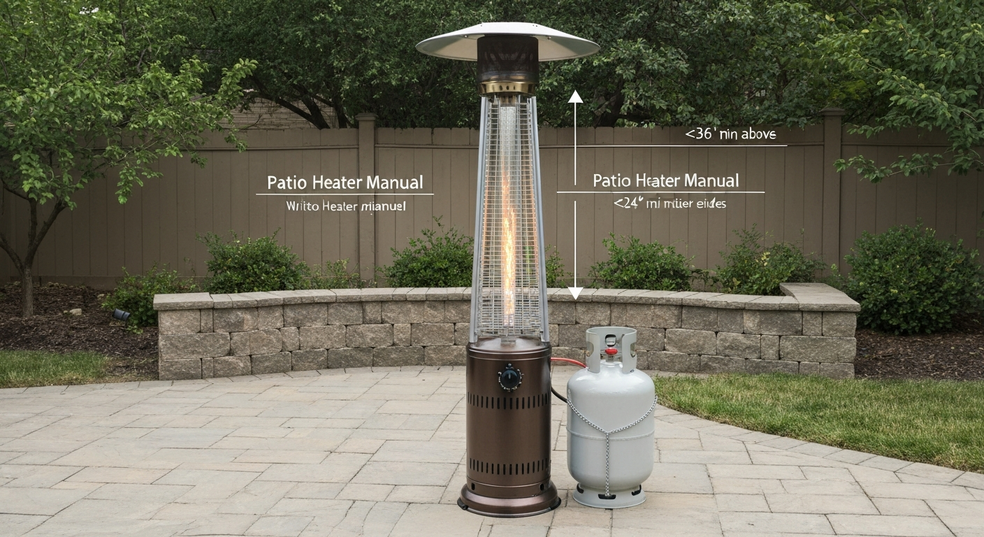
The OEM manual specifies minimum clearances to combustibles: 1,000 mm (approximately 36 inches) above the emitter head and 500 mm (approximately 24 inches) on all sides. Place the heater on a hard, level surface only, grass or uneven decking creates a tip-over risk and defeats the tilt-switch safety cutoff. Never obstruct the ventilation openings in the base housing or around the burner head.
Cylinder and regulator compatibility
Use a standard 20-lb propane cylinder (the OEM manual references this size throughout the assembly steps). The manual also states the cylinder must not exceed 15 kg maximum, which converts to approximately 33 lb, a standard 20-lb fill is well within this. Do not use a larger cylinder. Under NFPA 58, any refillable propane cylinder between roughly 4 and 40 lb capacity manufactured after the OPD cutoff date must have an Overfill Prevention Device (OPD) valve, these have a triangular handwheel. If your cylinder has the older round or star-pattern handwheel with no OPD markings, take it to a propane supplier for inspection before use; most suppliers won't refill them. The regulator supplied with the heater must comply with EN 16129 (or your applicable national standard). The OEM manual is explicit: replace the regulator and hose only with like-for-like parts. Do not substitute a BBQ-grill regulator, the pressure ratings differ.
Leak-test basics
Mix your leak-test solution now: 1 part liquid dish soap to 3 parts water. Apply it to every gas connection with a brush or sponge after the gas line is pressurized. If bubbles form, you have a leak. Never, under any circumstances, use an open flame to check for leaks. If a leak persists after tightening the fitting, shut the cylinder valve, disconnect the regulator, and contact Well Traveled Living's support line before using the heater. This is not a repair to force.
Full assembly, step by step
Follow these steps in order. Each step has a completion check so you know when to move on.
- Attach the wheel assembly to the base: align the wheel bracket holes with the base mounting points and secure with the large bolts and large nuts. Hand-tighten first, then snug with a wrench. Check: wheels roll freely and the base sits flat.
- Stand the lower post in the base housing. Slide the lower post into the base receptacle. Attach the three post supports — one at each of the three anchor points around the base — using the small bolts. The post supports brace the post at roughly a 45-degree angle. Check: post stands vertically without rocking.
- Route the gas hose down through the lower post before joining the upper post. This is the step most people miss. Thread the hose connector end down through the hollow post from the top so it exits at the base. You cannot do this after the posts are joined.
- Join the upper post to the lower post. Align the connection collar and secure with the small bolts and lock washers per the manual diagram. Snug firmly. Check: no rotation or wobble at the joint.
- Mount the head assembly to the top of the upper post using the small bolts and lock washers. The burner/control head has a defined orientation — the control knob faces the front. Align before tightening. Check: head is level and the control knob faces outward.
- Attach the four reflector panels to the reflector ring on the head assembly using the small screws (12 total, three per panel). Then seat the reflector center cap at the top of the reflector array and secure with the wing nuts (3). Check: panels are evenly spaced and center cap is flush.
- Place the propane cylinder inside the tank housing/base. Secure it with the chain provided — loop the chain through the designated bracket and fasten. Check: cylinder is upright and cannot tip inside the housing.
- Connect the gas hose to the burner inlet at the head end — the hose should already be routed through the post. Hand-tighten the fitting, then snug with a wrench (do not over-torque brass fittings).
- Attach the regulator to the free end of the hose and then thread the regulator outlet onto the cylinder valve. The cylinder valve is a standard left-hand (reverse) thread on U.S.-style tanks — turn counter-clockwise to tighten onto the tank. Snug firmly by hand or with a wrench. Check: regulator is firmly seated and the hose is not kinked.
At this point the heater is mechanically assembled. Before you open the cylinder valve, perform the full leak test described in the next section.
Gas hookup and first-time leak test
This is the most safety-critical part of the process. Work through it slowly and don't skip the bubble check.
- Confirm the control knob on the burner head is in the OFF position before opening the cylinder.
- Slowly open the cylinder valve one full turn counter-clockwise. You'll hear the regulator pressurize with a brief hiss — this is normal.
- Apply the soap solution generously to the regulator-to-hose connection and to the regulator-to-cylinder connection. Watch for 30 full seconds.
- If no bubbles appear at either connection, the seal is good. Proceed to startup.
- If bubbles appear at the regulator-to-cylinder joint: close the cylinder valve, remove the regulator, inspect the valve seat for debris or a damaged O-ring, reinstall and retest.
- If bubbles appear at the regulator-to-hose joint: close the cylinder valve, hand-tighten the hose fitting another quarter turn, retest.
- If bubbles persist after two tighten-and-retest cycles: do not use the heater. The hose or regulator fitting is damaged. Contact Well Traveled Living for a replacement hose/regulator assembly.
- Once leak-free, you can proceed to the ignition procedure.
A note on nominal inlet pressures: the OEM specification table lists 28–30 mbar and 37 mbar for G30/G31 LPG categories (roughly the pressures a properly functioning regulator delivers). You don't need to measure this yourself, but if you're ever sourcing a replacement regulator, make sure its output pressure matches the specification for your gas supply category, your propane supplier can confirm this.
Operating and ignition procedure
Standard startup
- Open the cylinder valve fully (turn counter-clockwise until it stops, then back a half-turn to prevent the valve from sticking).
- If this is the first light after a cylinder change or after the heater has sat unused, press and hold the control knob in for 2 minutes before attempting ignition. This purges air from the line. Skipping this step is the number-one reason a new cylinder won't light.
- Turn the control knob to the PILOT position and push it in to depress the safety valve.
- While holding the knob depressed, press the piezo igniter button repeatedly (up to 5–6 presses) until the pilot flame catches.
- Once the pilot is lit, continue holding the knob in for 30 seconds. This heats the thermocouple enough to hold the safety valve open.
- Release the knob slowly. If the pilot stays lit, rotate the knob to the LOW or HIGH position to bring up the main burner.
- If the pilot goes out when you release the knob, repeat from step 3. If it fails after three attempts, move to the troubleshooting section.
Shutdown procedure
- Turn the control knob to the OFF position to shut down the main burner and pilot.
- Close the cylinder valve by turning it clockwise until snug — do not force it.
- Allow the heater head to cool for at least 15 minutes before moving the unit.
- If storing the heater indoors or for an extended period, disconnect the regulator from the cylinder and store the cylinder outside in a ventilated area, never in a closed garage or basement.
Safe operating tips
- Never leave the heater unattended while running.
- Keep the heater away from overhangs, awnings, and umbrella canopies — the 36-inch top clearance is a minimum, not a target.
- The tilt switch will cut the gas if the heater leans more than roughly 30 degrees. If the heater shuts off unexpectedly, check that the surface is level before relighting.
- Never attempt to move the heater while the burner is running.
- Children and pets must be kept at a safe distance from the radiant emitter.
- Do not use the heater in high-wind conditions — the flame can become unstable and the heater is a tip-over risk.
Troubleshooting: common faults and how to fix them
Work through each symptom in order. The flowchart logic below is designed to take you from symptom to root cause in as few steps as possible, with the easiest checks first.
Fault 1: no spark when you press the igniter
- Check the igniter tip (electrode): look at the ceramic tip near the pilot assembly. If it's cracked, coated in heavy carbon, or the tip is missing, the electrode needs replacing.
- Check the gap between the electrode tip and the pilot hood: the gap should be roughly 3–4 mm. A gap that's too wide produces a weak or no spark. Carefully bend the bracket to correct it.
- Check for moisture: if the heater sat in rain, the electrode ceramic may be wet. Dry it with a cloth or low-heat hair dryer and retry.
- If none of the above fixes it: the piezo igniter module itself has failed. Replace the module. In the meantime, use a long-reach barbecue lighter or match at the pilot opening as a temporary workaround — the manual explicitly endorses this fallback.
Fault 2: spark is present but pilot won't catch
- Purge air from the line: hold the control knob depressed for 2 full minutes before trying again. After a cylinder change, air in the hose is the most common cause.
- Check gas supply: is the cylinder valve fully open? Is there fuel in the cylinder? A nearly empty cylinder often reads 'some pressure' but can't sustain ignition.
- Inspect the pilot orifice for blockage: insects (particularly spiders) nest in the pilot tube orifice during storage. Remove the head access cover and look into the pilot tube with a flashlight. Clear any debris with a thin wire or compressed air — never a wooden toothpick (it can break off).
- Check regulator function: if you've purged the line and the cylinder is full but still no gas smell at the pilot, the regulator may have tripped its excess-flow protection. Close the cylinder valve completely, wait 30 seconds, open it slowly again, and retry.
- If still no ignition after these steps: the problem may be a faulty regulator. Swap it with a known-good like-for-like unit and retest.
Fault 3: pilot lights but goes out when you release the knob
This is the classic thermocouple failure symptom. The thermocouple is a small metal probe that sits in the pilot flame. When it's hot, it generates a small millivolt signal (typically 15–30 mV for a standalone thermocouple) that holds the safety valve open. Honeywell and Robertshaw millivolt gas‑valve datasheets indicate some millivolt valves need around 18 mV minimum to hold, and thermopile generators are typically specified at roughly 500–750 mV open‑circuit Honeywell and Robertshaw millivolt gas‑valve datasheets indicate some millivolt valves need around 18 mV minimum to hold, and thermopile generators are typically specified at roughly 500–750 mV open‑circuit.. When it fails or is positioned incorrectly, the valve closes the moment you release the knob.
- Check thermocouple position first: the tip of the thermocouple must sit directly in the pilot flame. If it's been knocked out of position, bend it back so the tip is engulfed by the flame. Retry — hold the knob 45 seconds instead of 30.
- Test the thermocouple output with a multimeter: set to DC millivolts, attach the probes to the thermocouple connection terminals. Light the pilot and let it heat for 60 seconds. A healthy thermocouple should read 15 mV or higher. Readings below 10 mV indicate a failing unit. A reading of zero with the pilot lit means the thermocouple is dead.
- If the thermocouple reads low or zero: replace it. This is a 15-minute repair. Note the thread size on the connection nut before ordering (common sizes are 7/16-inch and M8x1.0 — measure yours). Universal thermocouples are sold at hardware stores for under $15.
- If the new thermocouple still won't hold the pilot: the problem has shifted to the gas valve safety seat. This is a valve replacement, which is a professional repair — see the 'when to call a pro' section.
Fault 4: pilot holds but main burner won't light or goes out shortly after
- Check for a thermopile (if your unit has one): some variants use a thermopile (a series of thermocouples generating 500–750 mV open-circuit) rather than a standalone thermocouple, to power the main gas valve. Test the thermopile at its connection terminals with your multimeter on the DC millivolt setting — a healthy thermopile reads 500 mV or higher open-circuit. Below 300 mV usually means it's failing; below 200 mV and it won't hold the main valve open.
- Check for low gas pressure: a partially open cylinder valve or a nearly empty cylinder can sustain the pilot but not the main burner. Open the valve fully and check cylinder weight.
- Inspect the main burner ports for blockage: carbon deposits or insect debris in the burner ring orifices cause uneven flame or no main burner ignition. Remove the emitter screen and inspect the burner ports. Clear gently with a soft brush or compressed air.
- If the thermopile tests weak: replace the thermopile assembly. This is slightly more involved than a thermocouple swap but still a manageable DIY repair. The thermopile connects to the gas valve with a push-in or screw terminal — photograph the wiring before disconnecting.
Fault 5: heater shuts off unexpectedly during operation (tilt-switch suspect)
- Check the surface: is the heater on a hard, level surface? Even slight unevenness can trip a sensitive tilt switch. Move the heater to a known-flat area and retry.
- Check the wheel assembly: a locked or stuck wheel can make the heater lean slightly. Confirm the wheels move freely.
- Test the tilt switch: locate the tilt switch (typically in the base or lower post area — it looks like a small cylindrical or ball-type switch in the gas circuit). With the heater fully upright and the gas off, check switch continuity with a multimeter set to resistance. A closed (good) switch reads near zero ohms. An open reading (infinity) when the heater is upright means the switch has failed in the open position and needs replacement.
- If the switch is fine and the heater still shuts off on a level surface: the problem is likely a thermocouple or thermopile issue causing intermittent valve closure, not a tilt-switch problem. Return to Fault 3 or 4.
Fault 6: burner produces black smoke or yellow, sooty flame
- Shut the heater down and let it cool.
- Remove the emitter screen (typically two or three screws) and inspect the burner ports for carbon deposits or spider nests.
- Clean the emitter screen and burner ports with a soft brush and compressed air. Do not use water on a hot burner.
- Check the injector orifice: the OEM specifies 1.90 mm for standard LPG categories. A partially blocked orifice produces a rich (yellow/sooty) flame. Clear carefully with a thin strand of wire — never drill or enlarge the orifice.
- Relight and observe: a properly burning flame should be blue with orange tips. Persistent black smoke after cleaning indicates a deeper blockage or a regulator delivering incorrect pressure — have the regulator tested.
Parts quick-reference table
Use this table to match a symptom to a part, understand what testing looks like, and gauge how difficult the repair is before you commit to it.
| Part | Symptom | Test method | Pass/fail criteria | Repair difficulty | Approx. time |
|---|---|---|---|---|---|
| Thermocouple | Pilot won't stay lit after releasing knob | Multimeter (DC mV) at thermocouple terminals with pilot lit | 15–30 mV healthy; below 10 mV failing; 0 mV = dead | Easy | 15–20 min |
| Thermopile | Main burner won't open / goes out | Multimeter (DC mV) at thermopile terminals with pilot lit | 500–750 mV open-circuit healthy; below 300 mV suspect; below 200 mV replace | Moderate | 20–30 min |
| Piezo igniter | No spark at pilot | Visual spark check in dim light; or continuity test on igniter lead | Visible spark = good; no spark = replace module | Easy | 10–15 min |
| Electrode / spark tip | No spark or weak spark | Visual inspection for cracks, carbon, correct gap (3–4 mm) | Clean ceramic, correct gap = good; cracked or wrong gap = adjust/replace | Easy | 10 min |
| Tilt switch | Heater shuts off on level surface | Multimeter continuity, heater upright, gas off | Near-zero ohms (closed) = good; open (infinite ohms) = replace | Moderate | 20–30 min |
| Regulator | No gas flow or weak flame despite full cylinder | Visual and functional: swap with known-good regulator | Normal flame = old regulator faulty; no change = look elsewhere | Easy | 5 min |
| Burner assembly / emitter | Yellow flame, black smoke, uneven heat | Visual inspection after cool-down; check ports and screen | Clear ports, clean screen = good; blocked = clean; cracked = replace | Moderate | 30–45 min |
| Gas hose | Smell of gas, bubbles on leak test | Soap-solution leak test at all connections | No bubbles = good; any bubble = replace hose | Easy (replace only — never repair a hose) | 10 min |
Troubleshooting flowchart (printable quick-reference)
Print this page and keep it with the heater. The logic moves from the most common and easiest-to-fix causes down to the less common ones. Work top to bottom before assuming you need a new part.
- SYMPTOM: Heater won't ignite at all (no spark) → Check electrode gap and condition → Clean or adjust gap → Still no spark? → Replace piezo igniter module → Use long-reach lighter as interim fallback.
- SYMPTOM: Spark present but pilot won't catch → Purge air (hold knob 2 min) → Check cylinder valve is fully open and cylinder has fuel → Inspect pilot orifice for insect/debris blockage → Clear orifice → Check regulator (swap test) → If still no ignition: replace regulator.
- SYMPTOM: Pilot lights but goes out when knob released → Check thermocouple position in flame → Test thermocouple output (need 15 mV minimum) → Replace thermocouple if below threshold → If new thermocouple still fails: gas valve safety seat issue — call a pro.
- SYMPTOM: Pilot holds but main burner won't open or goes out → Check cylinder is full and valve fully open → Test thermopile output (need 500+ mV) → Replace thermopile if below 300 mV → Inspect main burner ports for blockage.
- SYMPTOM: Heater shuts off mid-operation → Check surface is hard and level → Test tilt switch continuity (need near-zero ohms when upright) → Replace tilt switch if open → If switch is good: re-examine thermocouple/thermopile output.
- SYMPTOM: Black smoke / yellow sooty flame → Cool and inspect emitter screen and burner ports → Clean with brush and compressed air → Check injector orifice (1.90 mm standard) for partial blockage → Clear orifice → Persistent? Have regulator pressure tested.
- SYMPTOM: Smell of gas with heater off → Immediately close cylinder valve → Perform soap-solution leak test at all fittings → Bubbles at hose? Replace hose → Bubbles at regulator/cylinder joint? Tighten and retest → Leak persists: do not use — call Well Traveled Living support or a licensed LP gas technician.
Routine maintenance and seasonal storage checklist
A 15-minute inspection at the start and end of each season catches the problems that become costly mid-summer. This is also the right time to stock replacement parts so you're not ordering a thermocouple the same afternoon guests are arriving.
Start-of-season (spring) checklist
- Inspect the gas hose along its full length for cracks, kinks, or rodent damage. Replace if any damage is found — hoses are not repairable.
- Check the regulator connection O-ring for cracking or flattening. Replace if deformed.
- Inspect all bolted connections for looseness — vibration and thermal cycling loosen hardware over a storage season.
- Clean the emitter screen and burner ports with a soft brush. Spider nests in the pilot tube are the leading cause of first-season ignition failures.
- Check the reflector panels for dents or loose mounting screws — a damaged reflector affects heat distribution and can create uneven hot spots.
- Perform a full leak test before the first use of the season.
- Verify the cylinder has a valid OPD valve (triangular handwheel) and is within its re-certification date (typically stamped on the collar).
- Test the piezo igniter — fire three or four sparks. If it's weak or intermittent, replace it now rather than mid-season.
End-of-season (autumn/winter storage) checklist
- Shut off and disconnect the propane cylinder. Store the cylinder outdoors in a ventilated area — never inside a closed building.
- Clean the entire heater with a damp cloth. Let it dry fully before covering.
- Cover with a breathable patio heater cover (not an airtight plastic bag — trapped moisture accelerates corrosion).
- Store upright in a sheltered location. Laying the heater on its side can damage the burner assembly.
- Wrap the pilot tube opening loosely with a small cloth plug to deter insects from nesting — remove it before lighting next season.
Finding the official manual and replacement parts
The official AmazonBasics/Havana Bronze instruction manual is available as a PDF (published March 11, 2023) and can be found by searching the ASIN numbers B00LILH3V4, B010VFKZEO, or B07CH4XCTY on Amazon's product page documentation section, or by contacting Well Traveled Living directly, their phone number is printed on the last page of the manual. For an additional example of pilot-hold troubleshooting, see the uline tabletop patio heater instructions which cover the same thermocouple-holds-valve behavior. For OEM replacement parts, Well Traveled Living is the primary source for missing-hardware inquiries. For aftermarket thermocouples, piezo igniters, and regulators, standard hardware stores and fireplace/BBQ supply stores carry compatible universal parts, bring the thread size and connector type of your existing part when shopping.
If you're cross-referencing against a related heater that may share parts, Hampton Bay patio heater models are sold through Home Depot and use similar tower-heater architecture, though parts are not always interchangeable. For a direct comparison and hands-on evaluation, see our review hampton bay patio heater. See Hampton Bay outdoor/tabletop gas patio heater instructions for related assembly and troubleshooting guidance. See the Hampton Bay patio heater manual for model-specific assembly and parts details. The Hampton Bay 48,000 BTU stainless steel version and the Hampton Bay 31-inch outdoor gas heater are close cousins in design, and their manuals cover comparable assembly and troubleshooting logic. For specifics, consult the Hampton Bay 48,000 BTU stainless steel patio heater manual (search for 'hampton bay 48000 btu stainless steel patio heater manual'). For the Hampton Bay 31 in outdoor gas patio heater manual and model-specific parts information, consult Home Depot's product documentation for that model. The Uline tabletop patio heater uses a different burner scale but the same basic thermocouple-holds-valve mechanism, which makes its troubleshooting logic instructive for pilot-won't-hold symptoms on any brand.
When to stop and call a professional
Most Havana Bronze repairs are genuinely DIY-able. But there are clear lines where further tinkering becomes dangerous, and being honest about them is more useful than a generic disclaimer.
- You can smell gas with the cylinder valve closed. This means the regulator or a fitting upstream of the valve is leaking under residual line pressure. Do not attempt to find or repair the leak yourself — call a licensed LP gas technician.
- A new thermocouple doesn't hold the pilot. The gas valve safety seat is suspect. Gas valve internals require factory-trained service; replacement of the whole valve assembly is the correct repair.
- The regulator hose or body is visibly cracked, brittle, or has been exposed to flame. Replace only with an identical-spec unit; do not patch or tape a gas hose.
- Any repair that requires disconnecting a threaded gas fitting inside the burner head assembly (beyond the regulator and hose connections at the base) — these require a gas fitting tool and leak certification that goes beyond a DIY soap test.
- You've replaced the thermocouple, the thermopile, the igniter, and the regulator and the heater still won't operate normally. At this point the cost of further parts testing approaches or exceeds the cost of professional diagnosis — take it to a hearth/patio appliance shop.
The heater is certified to ANSI/CSA Z83.26 (CSA 2.37) for gas-fired outdoor infrared patio heaters, which means its safety devices (thermocouple, tilt switch, regulator) were tested as a system. Substituting non-certified replacement parts, especially the regulator, can compromise that system certification. When in doubt about part compatibility, call the Well Traveled Living support line listed in your manual.
FAQ
What official product manuals and source documents are essential to produce a fully accurate DIY instruction and troubleshooting guide for the Havana Bronze (AmazonBasics variant)?
- Official AmazonBasics / Havana Bronze instruction manual (46,000 BTU) PDF — includes assembly diagrams, parts list, safety warnings, leak‑test recipe, clearances, regulator/hose instructions, specifications and injector/orifice sizes. (https://ecx.images-amazon.com/images/I/C1VSAIAKf0S.pdf) - Alternate/manual mirror PDFs for cross‑checking (e.g., manuals.plus AmazonBasics Patio Heater manual). (https://manuals.plus/amazonbasics/46-000-btu-outdoor-propane-patio-heater-manual.pdf) - Manufacturer/parts support contact pages (Well Traveled Living / support phone number printed in manual). - Honeywell/Robertshaw technical notes and datasheets for millivolt valves, thermocouples and thermopiles to set electrical/voltage acceptance criteria (thermopile ~500–750 mV open circuit; thermocouple ~15–30 mV for pilot hold). (Robertshaw thermopile note: https://robertshaw.com/wp-content/uploads/2025/02/150-2379b-Thermopiles.pdf) - Gas‑heater standards and code references: NFPA 58 (LPG code) for cylinder/regulator/OPD and storage rules (https://www.nfpa.org/News-and-Research/Publications-and-media/NFPA-Journals/2024/NFPA-58-2024) and ANSI/CSA Z83.26 (gas‑fired outdoor infrared patio heaters) for design, clearances and safety device expectations (https://webstore.ansi.org/preview-pages/csa/preview_2423259.pdf). - Regulatory and OPD background reference (summary of OPD requirements). (https://legalclarity.org/opds-on-propane-cylinders-requirements-and-history/) These primary documents should be downloaded and archived so diagrams, parts counts, clearances and exact wording of warnings are reproduced verbatim where required.
Which model identification data and product specifics must be captured before writing instructions or troubleshooting steps?
- Exact model number(s) and ASIN(s) for each variant (e.g., Amazon ASINs B00LILH3V4, B010VFKZEO, B07CH4XCTY — confirm sticker/label on head assembly/base). - Serial number and production date if present on label (useful for parts compatibility). - Cataloged BTU rating and fuel type (e.g., 46,000 BTU, LPG/propane). - Official dimensional data (height, reflector diameter) and stated maximum cylinder size (manufacturer states standard 20 lb; manual also references 'Not to exceed 15 kg' / ~33 lb — capture both statements). - Injector/orifice sizes and gas‑category pressure tables from OEM spec page (e.g., injector diameters 1.90 mm for certain mbar ranges). Record these verbatim from the manual so torque, clearance and replacement parts match OEM requirements.
What hardware, parts and accessories lists are required for an accurate parts‑identification and sourcing section?
- Full OEM parts list from the manual showing every major assembly and hardware kit: reflector panels, reflector center cap, head assembly, burner/emitter screen, tank housing, upper/lower posts, post supports, base, wheel assembly, gas hose, regulator, chain, count of specific nuts/bolts/screws (wing nuts, cap nuts, large/small bolts/screws). - Functional parts to cover in troubleshooting table: thermocouple/thermopile (pilot generator), piezo igniter/electrode, electrode/ignition lead, tilt switch assembly, regulator (specification and OPD type), hose assembly, burner assembly/emitter, injector/orifice, control valve and pilot assembly. - OEM part numbers where printed in manual; if not present, high‑resolution photos of the part and measurements (thread size, connector type, tube diameter) to match aftermarket parts. - Vendor references and links for sourcing: OEM replacement via Amazon/Well Traveled Living support, common aftermarket suppliers (Hampton Bay/Uline cross‑reference pages), and generic parts vendors (e.g., plumbing/gas supply). Include authority for regulator matching (EN 16129 or national equivalent).
What specific technical data and test thresholds are required for electrical/multimeter diagnostics (thermocouple/thermopile/igniter)?
- Thermopile (pilot generator) expected open‑circuit voltage: ~500–750 mV for healthy assemblies (use Robertshaw spec as reference). - Thermocouple pilot‑hold expected voltage: ~15–30 mV under flame — millivolt valves often need minimum ~18 mV+ to hold (cite Honeywell/Robertshaw valve datasheets). - Suggested multimeter test procedures: measure open‑circuit millivolts at thermopile leads (with pilot lit), measure millivolts across thermocouple while holding pilot flame, measure continuity/resistance of piezo igniter electrode and tilt switch (in appropriate position), and measure voltage output of piezo lead only where applicable (piezo ignition is usually mechanical — check continuity/resistance of lead and electrode gap/grounding). - Clear pass/fail thresholds to use in troubleshooting flowcharts (e.g., thermopile <400 mV or thermocouple <12–15 mV → suspect failed assembly or poor pilot flame/cleaning/thermocouple replacement). Provide reference to Honeywell/Robertshaw docs for exact valve thresholds used.
Which safety, regulatory and prep checks must be included and cited verbatim in the guide?
- Clearance specifications from OEM manual: minimum top clearance 1000 mm (36 in), side clearance 500 mm (24 in); place on hard, level surface and do not obstruct ventilation openings. - Leak‑test recipe and procedure exactly as in manual: soap solution mix (1 part liquid dishwashing detergent to 3 parts water), apply to regulator/hose/tank fittings, open cylinder valve, inspect for bubbles, never use open flame to test leaks; if bubbles appear, shut off gas and tighten fittings and retest. - Regulator and hose instructions: use only the supplied regulator or an approved like‑for‑like replacement compliant with EN 16129 or applicable national standard; warnings about replacing with compatible parts only. - Cylinder guidance: use standard 20‑lb propane tank and do not exceed manufacturer’s stated maximum (manual references both ~20 lb and ‘not to exceed 15 kg’ — include both). Note OPD valve requirements where jurisdictional. - Code references to cite: NFPA 58 for LPG handling and storage; ANSI/CSA Z83.26 for heater design/clearance expectations. Include statement to follow local codes and to consult authorities having jurisdiction (AHJ) before permanent installations.
What photos, diagrams and labelled images are required for a truly actionable step‑by‑step assembly and troubleshooting guide?
- High‑resolution photos of model ID label and sticker locations (head and base) showing model/ASIN/serial numbers. - 'What’s in the box' flat‑lay photo with each hardware bag labelled to match OEM parts list. - Step‑by‑step assembly photos for each major stage with close‑ups of fastener orientation: wheel assembly to base, lower/upper post coupling, routing gas hose down through post, head assembly bolt pattern, reflector panel mounting and wing nut placement. - Diagrams/photos of hose routing inside post (cutaway or annotated photo) showing where hose should not kink and where to secure with clamps. - Detailed close‑ups of pilot assembly, thermocouple/thermopile attachment points, electrode/piezo tip gap and grounding, tilt switch location and mounting, burner/emitter screen and injector location. - Leak‑test photo sequence: applying soap solution to regulator/tank joint and to hose connections, and example photos of bubble patterns indicating leaks vs normal surface foam. - Ignition flow diagram: control knob positions, spark/piezo button location, recommended wait/purge times after tank change. - Troubleshooting flowcharts for common faults (no spark → check piezo → electrode gap → ground; failed ignition → check gas pressure/tank/regulator → clear pilot orifice → thermocouple output; won’t stay lit → thermocouple/thermopile voltage test → valve/regulator issues; tilt switch faults → continuity test and replacement). - Exploded view or annotated OEM parts illustration (from manual) to create a quick reference parts‑map image for ordering.