You can build or assemble a functional propane patio heater from certified components, but it is not quite the same as building a shelf or a planter box. Every gas-carrying part must be listed to a recognized safety standard (UL or CSA), your local authority having jurisdiction may require a permit, and the final assembly must follow the appliance manufacturer's instructions or an approved kit. If you go in with that understanding and the right parts, the actual assembly is well within reach for a careful DIYer with basic hand tools.
How to Make a Propane Patio Heater: DIY Build & Safety Guide

Grant Mercer
8 Aug 2026
Who this guide is for and what it covers
This guide is written for homeowners and confident DIYers who want to assemble, connect, test, and maintain a propane patio heater using standard, commercially available certified components. For clear, step-by-step propane patio heater instructions, consult the manufacturer's manual or a CSA-listed kit guide before you begin. Maybe you bought a heater as a kit without instructions, ordered parts to replace a wrecked unit, or just want to understand exactly how everything fits together before you light it for the first time. You do not need HVAC training to follow along, but you do need to take each step seriously because propane is unforgiving of shortcuts.
This article walks you through: what the safety standards and local codes actually require; a complete parts and tools checklist with specification requirements; how both mushroom/tower and umbrella/tube heater designs go together; connecting and leak-testing a propane cylinder; first-use commissioning; troubleshooting common failures like ignition problems, a heater that won't stay lit, tilt switch faults, and thermocouple issues; guidance on modifying heater height; a high-level look at fuel conversion; and an ongoing maintenance schedule. Where a task crosses the line into licensed-technician territory, this guide says so plainly.
Read this before you touch any part
Propane is heavier than air. It sinks to the ground, pools in low spots, and can ignite from a source well away from where the leak happened. A single unchecked fitting or cracked hose is enough to cause a fire or explosion. Carbon monoxide (CO) is a separate risk: any propane-burning appliance used in or near an enclosed space without adequate ventilation can produce fatal CO levels. These are not theoretical risks. Treat every gas connection as a potential failure point until you have tested and confirmed it is leak-free.
- NEVER use an open flame to check for gas leaks. Use only a soap-bubble solution or a listed combustible-gas detector.
- NEVER use propane heaters indoors, in garages, in tents, or in any partially enclosed space without engineered ventilation.
- NEVER modify a gas valve, orifice, or regulator unless you are using a manufacturer-supplied conversion kit with its own instructions.
- NEVER use components that are not listed to the applicable UL or CSA standard for LP-gas service.
- If you smell gas at any point during assembly, connection, or operation: shut off the cylinder valve immediately, move away from the area, and do not operate any electrical switches until the area is ventilated.
- Manufacturer manuals (including brands like Mr. Heater, Nexgrill, Hampton Bay, and Bromic) explicitly state that gas heater installation and service must be performed by a qualified or licensed gas technician when local code requires it. Check your local rules before proceeding.
Liability note: this guide provides general educational information based on recognized standards (ANSI/CSA Z83.26, NFPA 58, NFPA 54/ANSI Z223.1) and common manufacturer guidance. It does not replace your appliance's specific installation manual, your local building or fire code, or the advice of a licensed gas technician. Always defer to the instructions packaged with your specific heater and components.
Local codes, permits, and compliance
Before you buy a single part, spend 20 minutes checking what your local authority having jurisdiction (AHJ) requires. In the United States, most jurisdictions have adopted NFPA 58 (Liquefied Petroleum Gas Code) and NFPA 54/ANSI Z223.1 (National Fuel Gas Code) for LP-gas appliance installations. Some states, like New Jersey, have dedicated LP-Gas Safety Units that base technical requirements directly on NFPA 58. For example, the New Jersey Department of Community Affairs, Liquefied Petroleum Gas Safety Unit explicitly bases its LP technical requirements on NFPA 58 New Jersey Department of Community Affairs — Liquefied Petroleum Gas Safety Unit. Other jurisdictions use their own amendments. The rules that apply to you are the ones in force in your county or municipality, not a national average.
For a portable propane patio heater connected to a removable cylinder (the most common DIY scenario), many jurisdictions do not require a permit for residential use because the appliance is treated like a gas grill. However, if you are running a permanent gas line, using a large fixed LP tank, or installing a heater in a commercial or rental property, a permit and inspection are almost certainly required. The safest approach is to call your local building or fire department before you start and ask specifically whether a permit is needed for an outdoor propane patio heater installation.
- Call your local building department or fire marshal and describe the installation: portable vs. fixed, cylinder size, and whether it is residential or commercial.
- Ask which edition of NFPA 58 and NFPA 54 your jurisdiction has adopted, since different editions have slightly different requirements.
- If a permit is required, ask what documentation you need: appliance listing/certification, installation drawings, or inspection scheduling.
- Check HOA rules if applicable. Many homeowners associations restrict open-flame appliances on balconies or patios.
- Keep a copy of your appliance's certification (usually a CSA or UL listing mark on the data plate) for any permit application.
Parts, tools, and what 'listed' actually means
The single most important rule for gas appliance work is this: every component in the gas path must be listed (certified) to the applicable safety standard for LP-gas service. A part being sold at a hardware store does not mean it is listed for this application. Check the part itself or its packaging for a UL or CSA mark and the specific standard number.
Required standards for each component type
| Component | Required Listing/Standard | Notes |
|---|---|---|
| LP-gas hose | UL 21 or UL 569 | Replace only with hose listed to the same standard as original |
| Flexible hose connector / pigtail | UL 569 | Inspect for cracking, kinking, or abrasion before each use |
| LP-gas regulator | UL 144 or UL 252/252A | Consumer appliance regulators typically preset at ~11 in. W.C. outlet pressure for propane |
| Gas valve / control valve | ANSI Z21.21 / CSA 6.5 or manufacturer OEM | Do not substitute; use manufacturer-specified valve only |
| Burner assembly | CSA certified or OEM replacement | Orifice size is model-specific; do not substitute a different size |
| Igniter / piezo igniter | OEM or equivalent listed part | Match spark gap and wire length to original |
| Thermocouple / thermopile | OEM or equivalent millivolt-rated replacement | Thermocouple: ~20–35 mV; thermopile: ~250–750 mV — verify against your model's spec |
| Cylinder connection fitting | ANSI/CGA V-1 Type 1 (QCC1) for standard 20-lb cylinders | POL fittings exist on older equipment; confirm connector type in your manual |
| Propane cylinder | DOT specification, with OPD valve | 20-lb (approx. 5 gal) cylinders are standard for most consumer patio heaters; do not exceed the size rated for your appliance |
Tools checklist
- Adjustable wrench and open-end wrenches (typically 5/8", 3/4", 7/8" for gas fittings)
- Thread seal tape rated for gas service (yellow PTFE tape, not white plumbing tape)
- Dish soap and water in a spray bottle, or commercial leak-detection solution
- Digital multimeter capable of reading millivolts (for thermocouple/thermopile testing)
- Torque wrench (optional but helpful for consistent fitting tightness)
- Pipe thread sealant listed for gas service (if fitting type requires it)
- Screwdrivers (Phillips and flathead, multiple sizes)
- Hex/Allen key set
- Level (for confirming vertical plumb on tower-style heaters)
- Marker and tape measure
- Safety glasses and work gloves
How common propane patio heaters are designed
Almost every consumer propane patio heater falls into one of two design families, and they assemble quite differently. Knowing which type you have before you start saves a lot of confusion when the instructions reference parts that do not seem to match what is in front of you.
Mushroom/tower style
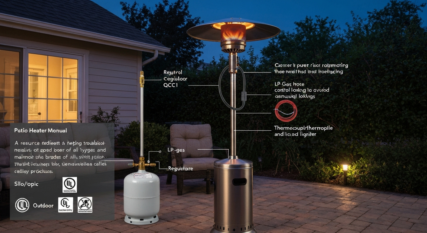
This is the tall freestanding heater you see at restaurants and on residential patios. It typically stands 7 to 9 feet tall, has a cylindrical base that houses the propane cylinder, a pole made of two or three stackable sections, and a dome-shaped emitter head at the top. Heat radiates outward in a 360-degree pattern from the burner ring mounted just below the dome. The tilt safety switch is usually mounted in the base or lower pole section. Input ratings for consumer models typically run from about 40,000 to 48,000 BTU/hr. These heaters are the most DIY-friendly to assemble because the modular pole sections bolt or clip together and all gas connections happen at the base and at the burner head.
Umbrella/tube style
The umbrella or tube style mounts to a wall bracket, a post, or fits through the center hole of a patio table. The burner fires upward or downward through a single tube, and a heat deflector (the 'umbrella') spreads radiant heat outward. These are more compact and often used where a freestanding unit is impractical. The gas connections are typically at the bottom of the tube, and the cylinder may hang from a bracket or sit in a separate holder. Assembly is generally simpler because there are fewer pole sections, but mounting and leveling the bracket correctly is critical for tilt-switch operation and stability.
| Feature | Mushroom/Tower | Umbrella/Tube |
|---|---|---|
| Heat pattern | 360-degree radiant from top dome | Directional or partial-circle from tube/deflector |
| Typical BTU input | 40,000–48,000 BTU/hr | 10,000–40,000 BTU/hr depending on model |
| Height | 7–9 ft freestanding | Variable; wall/post/table mounted |
| Cylinder location | Inside or beside base | Separate holder or hanging bracket |
| Assembly complexity | Moderate (3–4 pole sections) | Lower (fewer sections, but mounting required) |
| Tilt switch location | Base or lower pole | Base bracket or lower tube section |
| Best for | Open patios, large coverage areas | Covered patios, tables, tight spaces |
One compatibility note worth flagging: burner heads, orifices, and regulators are not interchangeable between designs or between brands. A burner ring sized for a 46,000 BTU/hr tower heater will not work correctly on a 20,000 BTU/hr tube-style unit. Always use the OEM replacement parts specified in your heater's manual, or a CSA-listed equivalent with identical gas input ratings.
Assembling a mushroom/tower-style heater
Before you start, lay all parts out on a clean flat surface and match them to the parts diagram in your manual. Do not rely on the assembly video alone. Count everything. Missing a single bolt or failing to route the gas hose correctly through the pole before connecting it is a very common mistake that means disassembly and starting over.
Parts layout and pre-assembly check
- Confirm the base unit, all pole sections (typically labeled lower, middle, upper or 1/2/3), the emitter head assembly, and the dome/reflector are all present.
- Locate the gas hose/regulator assembly, control valve, burner ring assembly, thermocouple or thermopile lead, igniter wire, and all hardware bags.
- Inspect the hose for any cuts, kinks, or abrasion from shipping. If the hose is damaged in any way, do not use it. Order a replacement listed to UL 21 or UL 569.
- Check that the regulator carries a UL 144 or UL 252 listing mark. If the unit came without a regulator, source one preset to approximately 11 in. W.C. outlet pressure for propane, listed to UL 144.
Assembly sequence
- Assemble the base: attach the wheel casters or leg feet per the manual. Most bolt directly into threaded inserts in the base casting. Do not overtighten plastic inserts; hand-tight plus a quarter turn is usually sufficient.
- Thread the gas hose up through the lower pole section BEFORE attaching the lower pole to the base. This is the most commonly skipped step, and it forces complete disassembly if missed.
- Attach the lower pole to the base flange using the provided bolts. If the manual specifies a torque value, use a torque wrench. If not, snug the bolts and add about a half-turn of additional torque — do not overtighten aluminum pole flanges.
- Stack the middle and upper pole sections, routing the igniter wire and thermocouple lead up through the interior of each section as you go. Most designs have a small notch or clip inside the pole sections to hold these wires against the wall so they do not rub on the gas hose.
- Connect the gas hose to the control valve at the burner head assembly. Use yellow gas-rated PTFE tape on male NPT threads only (do not tape flare fittings). Tighten fittings hand-tight first, then snug with a wrench — typically 1.5 to 2 full turns past hand-tight for tapered NPT connections.
- Mount the burner head assembly to the top pole section per the manual. Connect the igniter wire and thermocouple/thermopile leads to their respective terminals. The thermocouple tip must be positioned in the pilot flame path as specified in the manual — usually within 3/8 to 1/2 inch of the pilot orifice.
- Attach the dome reflector and any accent ring hardware.
- Connect the lower end of the gas hose to the regulator assembly, then connect the regulator to the cylinder valve fitting. Do not open the cylinder valve yet.
- Perform a full leak test (detailed in the tank connection section below) before proceeding to first light.
A note on thread sealant: use yellow gas-rated PTFE tape or a pipe dope listed for LP-gas service on all male NPT (tapered pipe) threads. Do not use sealant on flare fittings or on the QCC1 cylinder connector, which relies on a rubber O-ring or seat for its seal. Applying tape to a QCC1 male connector is a mistake that can actually prevent a proper seal.
Assembling an umbrella/tube-style heater
The tube-style heater's assembly is shorter but the mounting step is where most problems occur. A bracket that is not plumb will trip the tilt switch during normal operation and cause the heater to shut off, which is a common frustration that gets misdiagnosed as a thermocouple or valve problem.
Parts layout and pre-assembly check
- Identify the main tube/burner assembly, the umbrella/deflector, the mounting bracket and all hardware, the gas hose and regulator, and the cylinder holder or bracket if included.
- Check the wall or post where the bracket will mount. It must be a structurally sound surface: masonry, solid wood framing, or a steel post. Do not mount to drywall or hollow-core siding alone.
- Confirm the mounting surface is a non-combustible material or verify that the clearance to combustibles meets the manufacturer's specification. Most tube-style heaters require a minimum of 24 to 36 inches of clearance from the mounting surface to combustibles above or beside the emitter.
Assembly and mounting sequence
- Assemble the tube sections together on the ground first. Route the gas hose, igniter wire, and thermocouple lead through the tube before joining sections.
- Connect the gas hose to the burner/control valve assembly at the top of the tube. Apply gas-rated PTFE tape to NPT threads and tighten as described above.
- Use a level to mark the mounting bracket position on the wall or post. The tube must hang vertically plumb. Even a few degrees of tilt can engage the tilt switch during operation.
- Drill pilot holes and use fasteners rated for the mounting surface: lag screws into wood framing, masonry anchors for concrete or brick. Use at least two mounting points to resist lateral movement.
- Hang the tube assembly on the bracket and secure with the locking pin or bolt per the manual.
- Mount the cylinder holder at the appropriate height and secure it so the cylinder stands vertical and is stable.
- Route the hose from the burner down to the regulator and cylinder connection, ensuring the hose does not contact the hot tube during operation and has no sharp bends or kinks.
- Perform a full leak test before lighting.
Connecting the propane tank
This is the part of the process that causes the most DIY errors, mostly because of incorrect assumptions about fittings and regulators. Spend a few extra minutes here and you will avoid a lot of problems later. For step-by-step instructions on how to connect propane tank to patio heater, see the how to connect propane tank to patio heater guide.
Selecting the right regulator
Consumer propane patio heaters use a two-stage or appliance regulator that reduces cylinder pressure (which can be over 100 PSI depending on temperature) down to the appliance operating pressure, typically approximately 11 inches of water column (in. W.C.) for most consumer patio heaters. The regulator must be listed to UL 144 or UL 252/252A. See the UL 147 listing for related component standards, which references UL 21, UL 569, UL 144, UL 252/252A and other applicable LP‑gas component standards (UL 147 page referencing UL 21, UL 569, UL 144, UL 252, etc.). Do not substitute a natural gas regulator, an industrial LP regulator, or a regulator from a different appliance category. If the regulator that came with your heater is cracked, corroded, or more than 10 years old, replace it with a manufacturer-specified or equivalent UL-listed part before using the heater.
Cylinder types, fittings, and what to avoid
Standard consumer patio heaters in the U.S. are designed to connect to a DOT-specification propane cylinder using a Type 1 / QCC1 (ACME quarter-turn) connector per ANSI/CGA V-1. This is the same fitting used on standard 20-lb propane grill cylinders. The QCC1 connector threads onto the cylinder valve in a clockwise direction (right-hand thread) and seals on a rubber seat inside the fitting. It requires no tools for installation, just hand-tight, which is intentional.
- Use only DOT-specification cylinders with an OPD (Overfill Prevention Device) valve. OPD valves have a triangular handwheel. If your cylinder has a round or star-shaped handwheel, it is an older cylinder without an OPD and many retailers will not fill it.
- Standard consumer patio heaters are rated for 20-lb cylinders (approximately 4.7 gallons). Do not connect a larger tank without confirming your appliance is rated for it.
- Do not use a POL fitting adapter to connect a QCC1 regulator to an old POL-style cylinder. If your cylinder is old enough to have a POL valve, it needs to be recertified or replaced.
- Do not use pipe thread adapters or DIY fittings to connect mismatched components. If your hose and cylinder do not mate directly, you have either the wrong hose or the wrong cylinder.
- Cylinders must be requalified every 10 to 12 years (the requalification date is stamped on the collar). A filling station will refuse to fill an expired cylinder.
Making the connection and performing the leak test
- Place the cylinder on a flat, level, stable surface. For tower-style heaters, this is usually inside the base cabinet. The cylinder must remain upright at all times during use.
- Thread the QCC1 connector onto the cylinder valve handwheel clockwise (right-hand thread) until hand-tight. Do not use a wrench on the QCC1 nut itself.
- Make sure the control knob on the heater is in the OFF position.
- Slowly open the cylinder valve one full turn counterclockwise. Do not fully open it all the way; one full turn is sufficient for operation and allows you to close it quickly if needed.
- Mix a solution of dish soap and water in a spray bottle, or use a commercial leak-detection solution. Spray or brush the solution generously onto every connection: the cylinder valve/QCC1 joint, the regulator body and both ends of the hose, and the burner head connection at the top.
- Watch each connection point for 30 seconds. Bubbles forming at any joint indicate a leak. If you see bubbles, close the cylinder valve immediately, disconnect and remake the connection, then re-test.
- If a joint continues to leak after remaking the connection, the fitting, hose, or regulator is defective. Do not operate the heater. Replace the defective component.
- If all joints are bubble-free for 30 seconds after the valve is opened, the system is gas-tight and you are ready for the first-use test.
Cylinder storage and handling
Store propane cylinders outdoors in a vertical position, away from ignition sources, heat above 120°F, and enclosed spaces. Never store a connected or disconnected LP cylinder indoors, in a vehicle, or in a garage. When transporting cylinders, keep them upright and secured in a ventilated area of the vehicle (trunk open or truck bed), and never leave a cylinder in a sealed car on a hot day.
First-use checklist and safe commissioning
The first time you light a newly assembled heater, work through this checklist methodically. Do not rush it. The first firing is your best opportunity to catch any assembly error before it becomes a problem.
- Confirm the heater is positioned outdoors with the clearances specified in your manual. Most mushroom/tower heaters require a minimum of 24 to 36 inches clearance from any combustible surface on all sides, and 36 inches or more above.
- Confirm the surface under the heater is stable and level. For tower-style heaters, verify the tilt switch is in its normal (upright) position by consulting the manual.
- Confirm the cylinder valve is closed and the control knob is in the OFF position.
- Open the cylinder valve one full turn and perform the soap-bubble leak test one more time at all connections.
- Follow the lighting procedure in your manual exactly. Most consumer heaters use a push-and-turn ignition: push in and turn to the PILOT position, hold in for 30 seconds to heat the thermocouple, then try the igniter. If the pilot does not light in three attempts, wait five minutes before trying again to allow any accumulated gas to dissipate.
- Once the pilot is established and the main burner lights, observe the flame quality for two minutes. The flame should be steady blue with small yellow tips on the outer edges. A predominantly yellow or orange flame can indicate an air shutter problem or dirty burner, not a gas pressure issue.
- Walk around the heater and verify that heat is radiating normally and that no part of the assembly is vibrating, rattling loose, or making unusual sounds.
- Mark the assembly date on the base of the heater with a permanent marker, and store your manual and parts documentation in a safe place.
Troubleshooting: the most common problems and how to fix them
Igniter clicks but pilot won't light
First, confirm the cylinder has fuel and the valve is open. Then check whether you can smell any gas when the control knob is turned to PILOT. If you smell nothing, the issue is gas delivery: check the regulator for a tripped excess-flow device (this can happen if the valve was opened too quickly), close the cylinder valve fully, wait 30 seconds, then reopen it slowly. If gas is flowing but the spark is not igniting it, inspect the spark electrode tip and wire. The electrode gap should typically be around 1/8 to 3/16 inch from the pilot burner hood. Carbon buildup on the electrode tip can be cleaned carefully with fine-grit sandpaper. Check that the igniter wire is fully seated and not cracked or corroded at either end.
Pilot lights but won't stay lit when button is released
This is almost always a thermocouple problem. The thermocouple is a small sensor probe that sits in the pilot flame. When heated, it generates a small electrical voltage (typically 20 to 35 millivolts for a single thermocouple) that signals the gas valve to stay open. If the thermocouple is dirty, damaged, or positioned incorrectly so it is not fully engulfed by the pilot flame, its output voltage drops below the valve's hold-open threshold and the valve closes. To test: with the pilot lit and the control button held in, use a multimeter set to the millivolt DC range and measure the thermocouple output at the valve connection. If you read below about 15 mV, the thermocouple needs replacement. If output is in the normal range but the pilot still drops out, the valve itself may be faulty. Thermocouple replacement is a straightforward DIY repair that does not require disassembling the gas path.
Heater shuts off randomly during operation
Random shutoffs during normal operation are most commonly caused by one of three things: a tilt switch fault, a low-gas condition, or a thermopile output problem. Check the tilt switch first by confirming the heater is on a level surface and that the switch mechanism (usually a ball-bearing type) has not seized in the tripped position. You can test continuity across the tilt switch with a multimeter; a functioning switch should show continuity when the heater is upright and an open circuit when tilted. If the switch tests good and the cylinder has adequate fuel, test the thermopile output. Thermopiles generate higher millivolt outputs than single thermocouples (typically 250 to 750 mV) to operate millivolt gas valve controls. Measure the output with a multimeter at the valve terminal while the pilot is running. If your reading is below the minimum specified in your manual, the thermopile needs replacement. If both the tilt switch and thermopile test good, the issue is likely the gas control valve itself, which is a manufacturer-specified replacement job.
Weak or uneven flame pattern
A burner ring that produces uneven heat is usually a clogged orifice or spider-web debris in the burner ports. Turn off and disconnect the cylinder, allow the heater to cool fully, then remove the burner head assembly per the manual. Inspect the burner ring ports with a flashlight. Do not use a metal probe to clear clogged ports as this enlarges the orifice and changes the gas input rating. Use compressed air or a soft brush. While you have the head apart, check that the air shutter opening is set to the manufacturer's specification. On most consumer heaters, the air shutter is fixed and not field-adjustable, but debris can partially block it.
Modifying heater height: what's practical and what's not
If your heater is too tall for a covered patio or pergola, shortening the pole is a commonly sought modification. The practical reality is that shortening the decorative non-gas-carrying pole sections is feasible as a DIY project if done carefully. However, shortening a section that contains the gas hose run-through changes the hose length, and if the hose runs inside the pole, you will need to replace it with a properly sized UL 21 or UL 569 listed hose. Never splice a gas hose to add length or shorten it.
The absolute limits are these: you cannot shorten the pole below the minimum height that maintains the manufacturer's required clearance between the burner head and any combustible surface below or around it. Reducing pole height below that threshold is an unlisted modification and a genuine fire risk. Check the clearance table in your manual before cutting anything. Tube/umbrella heaters with a single pole section are generally not safely shortenable by field modification.
Converting to natural gas: what you can and can't do yourself
Some propane patio heaters can be converted to natural gas, but only using a manufacturer-supplied and approved conversion kit. ANSI/CSA Z83.26, the governing standard for gas-fired outdoor infrared patio heaters, permits fuel conversion only when the manufacturer provides an approved kit with its own instructions (Annex D of the standard). There is no such thing as a generic, safe 'just swap the orifice' conversion for a patio heater. For step-by-step guidance and manufacturer-approved options, see can you convert propane patio heater to natural gas. A propane orifice is significantly smaller than a natural gas orifice for the same BTU output because LP has a higher energy density and different pressure, and mixing up orifice sizes either starves the burner or creates a dangerously rich mixture.
If your heater manufacturer offers a conversion kit, the kit will include a replacement orifice, a new regulator or orifice fitting sized for natural gas pressure (typically 3.5 in. W.C. for NG), and explicit instructions. Even with an approved kit, the natural gas connection itself (connecting to a fixed gas line) typically requires a licensed gas technician and a permit in most jurisdictions. Do not connect a patio heater to a natural gas supply line yourself unless you are a licensed gas fitter.
Maintenance and annual inspection schedule
A patio heater that is serviced once a year and checked before every season of use will last significantly longer and perform more safely than one that is ignored until something goes wrong. This is not a complex maintenance job; it takes about 30 minutes.
| Task | Frequency | What to check |
|---|---|---|
| Visual hose inspection | Before each use | No cracks, kinks, abrasion, or discoloration; ends fully seated |
| Leak test at all connections | Before each use after storage or reconnection | Soap-bubble test; no bubbles at any fitting |
| Burner port inspection | Start of each season | Clear of debris, spider webs, corrosion |
| Thermocouple/thermopile check | Annually or if pilot won't hold | Millivolt output within manufacturer's spec |
| Tilt switch function test | Annually | Continuity when upright; open circuit when tilted |
| Regulator inspection | Annually | No cracks, corrosion, or physical damage; replace if over 10 years old |
| Cylinder condition and date | Each refill | DOT spec, OPD valve, within requalification date, no damage |
| Electrode and igniter wire | Annually | Correct gap, no carbon buildup, wire insulation intact |
| Structural hardware | Annually | All bolts snug; no corrosion at pole flanges or bracket mounts |
| Dome and reflector | Annually | No warping, cracks, or discoloration indicating overheating |
Should you build from parts, buy a kit, or hire a pro?
Building a patio heater entirely from individual components is not the right move for most homeowners. The certification requirements for each component, the need to match orifice sizes and BTU ratings, and the liability of an unlisted assembly make a fully custom build both technically complex and legally murky. The better DIY path is to start with a complete, CSA-listed heater kit or a commercial unit, assemble it precisely per the manufacturer's instructions using the supplied components, and replace any worn parts with manufacturer-specified or equivalent listed replacements.
Hire a licensed gas technician if: you are connecting to a permanent natural gas line, your local code requires licensed installation for LP appliances, you are installing in a commercial or rental property, or any gas component tests outside the manufacturer's specification and you are not confident identifying the correct replacement. The cost of a service call is far lower than the cost of a propane-related incident.
For everything in between, including assembly, leak testing, thermocouple replacement, burner cleaning, and troubleshooting ignition problems, a careful DIYer with the right parts, the manufacturer's manual, and this guide can handle the work safely. Keep your documentation, know where your gas shutoff is, and never rush a gas connection.
FAQ
What core consensus standards and model codes must be consulted to make a safe, code‑compliant DIY guide for propane patio heaters?
At minimum consult: ANSI/CSA Z83.26 / CSA 2.37 (patio‑heater appliance standard) for appliance classifications, clearances, input ratings and manufacturer conversion kit rules; NFPA 58 (Liquefied Petroleum Gas Code) for LP‑gas design/installation/inspection and permitting practices; and NFPA 54 / ANSI Z223.1 (National Fuel Gas Code) for piping, connectors and appliance installation details. These are the primary authoritative references that AHJs commonly adopt — always identify the version locally adopted by the authority having jurisdiction (AHJ).
Which manufacturer and OEM documents are required source material?
Collect the exact installation, service and parts manuals for every model you discuss (examples: Bromic, Mr. Heater, Nexgrill, Detroit Radiant, Hampton Bay). Manufacturer manuals provide model‑specific clearances, burner/orifice sizes, regulator settings, approved replacement parts, and explicit warnings about prohibited alterations and required qualified servicing. Use the OEM manual as the authoritative source when giving model‑level instructions and always quote clearance tables and part numbers directly from that manual.
What component standards and listings must parts meet (hose, regulator, fittings, valves)?
Specify only components listed to the applicable ANSI/UL/CSA standards for gas appliance parts: e.g., UL 21 or UL 569 for LP hoses/pigtails, UL 144 for LP regulators, and other relevant UL/CSA listings for valves/fittings. Require replacement assemblies to be identical to the original listed assembly or a manufacturer‑approved substitute. Cite the relevant standard/listing and the OEM part number when possible.
What cylinder and connector specifications should be required in the guide?
Require DOT‑spec (or CAN/CSA equivalent) propane cylinders with OPD (overfill prevention device) for small consumer tanks. Identify the cylinder valve type used by each heater model (Type‑1/QCC1 ACME/quarter‑turn is the common U.S. consumer standard; older POL connections still exist). Never recommend adapters that bypass required safety devices — always direct readers to OEM guidance on acceptable tank sizes and connector types.
What approved procedures must be included for connecting a propane tank and conducting a leak test?
Describe correct regulator/hose assembly installation using only listed parts, hand‑tightening then final torque per OEM if specified, then perform a soap‑bubble leak test (dish soap/water or commercial leak‑detection fluid) at all fittings with the supply valve opened slowly. Explicitly prohibit using an open flame to test leaks. Advise supplementing with a listed combustible‑gas detector for commissioning or troubleshooting when available.
What thermocouple/thermopile and ignition test information should be provided for troubleshooting?
Provide millivolt testing guidance: typical thermocouples produce ~20–35 mV, thermopiles ~250–750 mV — but require the appliance manufacturer’s accept/reject thresholds for diagnosis. Instruct readers to use a multimeter to measure open‑circuit millivolts per the OEM manual, and to compare readings to the model‑specific service limits. Emphasize that ignition/electronic control modules and replacements should be OEM or listed equivalents.