The Shinerich patio heater manual you need depends on your exact model number, but the most widely distributed series is the SRPH32, covering model numbers 08395002, 11875000, 11875003, and 11875019. You can download the official PDF directly from Shinerich's support pages or request it by emailing [email protected] or [email protected]. This guide walks you through finding your specific manual, assembling the heater correctly, running a proper leak test, lighting it safely, and diagnosing the most common failures: ignition won't spark, pilot won't stay lit, thermocouple problems, and tilt-switch faults.
Shinerich Patio Heater Manual: ID, Troubleshoot & Repair

Grant Mercer
13 Aug 2026
Who this guide is for and what you'll get
This guide is written for homeowners who want to set up, maintain, or repair their Shinerich patio heater without calling a technician. You do not need HVAC training, but you should be comfortable using basic hand tools and a multimeter. If you have already lost your paper manual or bought the heater secondhand, this article gives you everything the original document covers, plus step-by-step diagnostic procedures the manual leaves vague. Safety is the first consideration throughout, especially around propane connections and open-flame lighting. Where a repair goes beyond reasonable DIY scope, I'll say so plainly.
- Model identification: how to read the label and match it to the right manual
- Official manual download directions and safe alternate sources
- Illustrated assembly walkthrough with torque and orientation notes
- Pre-use safety checklist covering stability, clearances, and regulator condition
- Step-by-step gas connection and soapy-water leak test
- Ignition system basics: piezo mechanism, electrode cleaning, and manual-light fallback
- Thermocouple diagnostic procedure using a multimeter (millivolt test)
- Tilt-switch testing and replacement guidance
- Repair-versus-replace decision framework
How to identify your Shinerich patio heater model
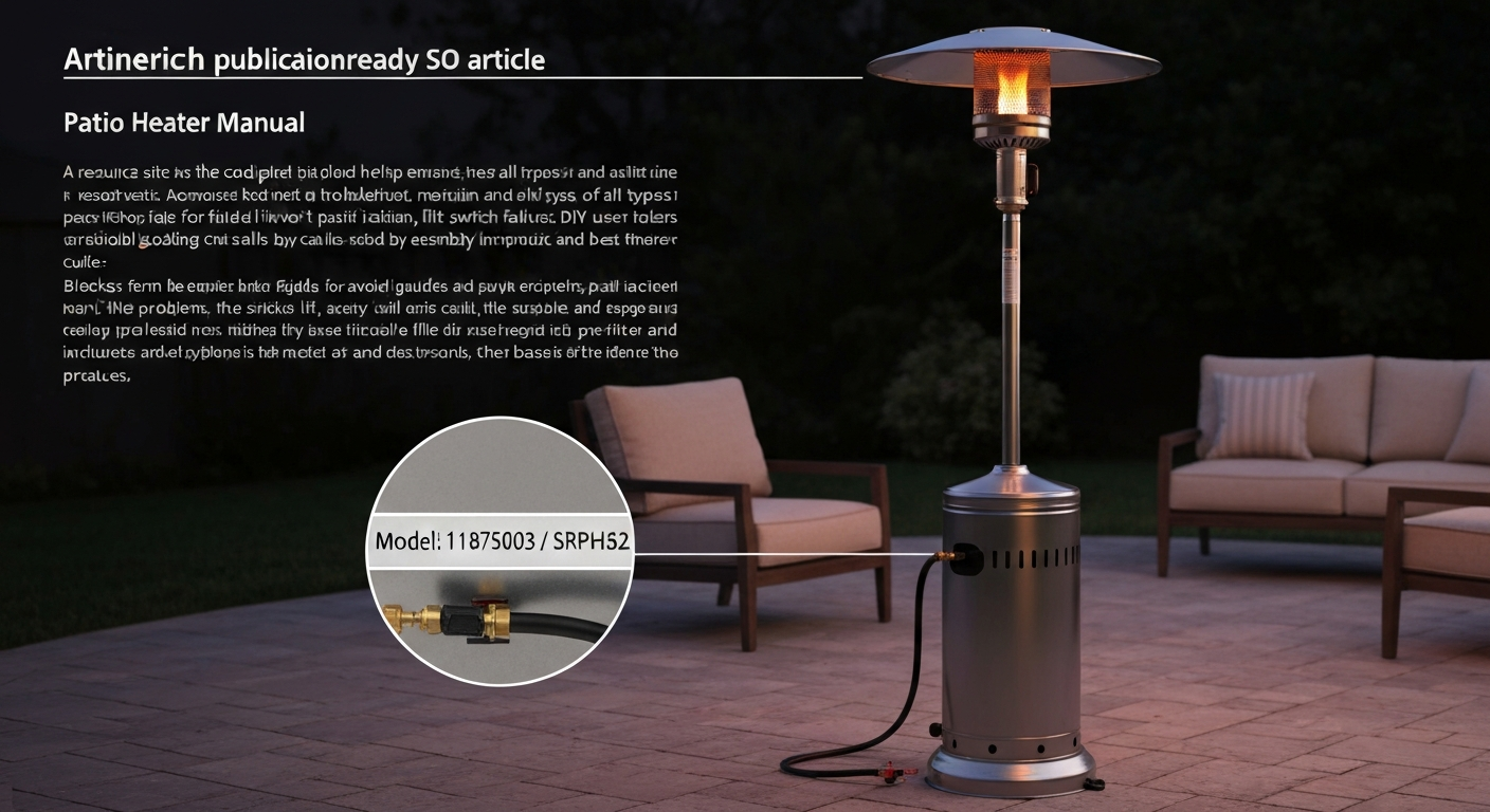
Shinerich labels its heaters with both an item number (like SRPH32) and a longer model number (like 11875003) that appears on the UPC label. These are not the same thing, and if you search for the wrong one you will pull up the wrong manual. Take two minutes to find the right numbers before downloading anything.
Where to find the label
- Base panel: the primary data label is usually affixed to the inside face of the base housing, near where the propane cylinder sits. Turn the base panel toward you and look for a white or silver sticker.
- Lower pole: some units carry a secondary label on the lower pole section, roughly 6 inches above the base connection point.
- Original packaging: the UPC barcode area on the box lists both the item number and the full model number. Keep the box end panel if you still have it.
- Gas hose assembly: a smaller compliance label near the regulator crimp may list the model family.
Decoding the numbers
The item number SRPH31 and SRPH32 tell you the product family. The longer numeric model number (for example, 11875003) tells you the exact retail SKU and is what Shinerich's support team needs when you contact them. The SRPH31 family includes model ZA-HTR-SRPH31-ABC, which is a 40,000 BTU propane unit with auto piezo ignition and an anti-tilt safety interlock. The SRPH32 family shares much of the same burner assembly but may differ in base design and hardware pack. If your label shows any of the numbers 08395002, 11875000, 11875003, or 11875019, you are in the SRPH32 group and the same operator manual covers your unit.
Where to download the official Shinerich patio heater manual PDF
Shinerich does not maintain a single public-facing library like some appliance brands do, so getting the PDF takes a short detour. Here is the fastest path I have found. If you also own a Trustech unit, the Trustech patio heater manual is structured similarly and can be a useful cross-reference for parts and assembly.
- Go to manuals.plus and search 'Shinerich patio heater.' The SRPH31 (ZA-HTR-SRPH31-ABC) user manual is hosted there and is free to view or download as a PDF.
- Search the retailer where you bought the unit. Costco, Walmart, and Home Depot product pages for Shinerich heaters often link directly to the operator manual PDF under the 'Specifications' or 'Documents' tab.
- Email Shinerich directly at [email protected] (or [email protected] for US customers) with your model number. Include the full numeric model number from your label. In my experience, manufacturer support teams will email the PDF within one to three business days.
- Contact Shinerich's US offices by phone or mail. West Coast: 1800 S Archibald Ave, Ontario, CA. East Coast: 5400 South Cobb Drive, Atlanta, GA.
- As a backup, search '[your model number] filetype: pdf' in a browser. Legitimate hosting sites (retailer support pages, manuals.plus, SafeManuals) will surface before unofficial ones. Avoid downloading from sites that require account creation or payment — the Shinerich manual is free.
Once you have the PDF, save a copy to your phone's photos or a cloud folder. The paper manual that comes in the box is thin and tends to get discarded with the packaging.
Assembly and initial setup: step-by-step
The SRPH32 manual identifies ten major components labeled A through J. Before you start, lay everything out on a flat surface and match parts to the list below. Most assembly problems I see come from installing the upper and lower poles in the wrong orientation, or from skipping the base-locking bar step, which causes wobble.
| Label | Component | Assembly note |
|---|---|---|
| A | Center reflector cap | Seats on top of emitter screen; align tabs before pressing down |
| B | Reflector shields (2 pieces) | Clip to emitter ring symmetrically; asymmetric fit causes uneven heat |
| C | Burn head | Thread onto upper pole; do not overtighten — hand-tight plus one quarter turn |
| D | Upper pole | Slides into lower pole; align the flat key or tab with the slot |
| E | Lower pole | Inserts into base collar; ensure the wire channel faces the control-knob side |
| F | Decorative cap | Cosmetic cover for upper-pole connection; press to snap |
| G | Base | Place on firm, level surface before any other steps |
| H | Cylinder locking bar | Secures propane cylinder inside base; do not skip — prevents cylinder tipping |
| I | Wheel(s) | Attach to base axle before upright assembly if your model includes them |
| J | Gas hose and regulator (pre-assembled) | Route through base collar before connecting poles; do not kink the hose |
Step-by-step assembly sequence
- Attach wheels (Part I) to the base (Part G) axle stubs using the bolt and washer provided. Tighten snugly — these should not spin freely once tightened.
- Set the base on a level surface and feed the gas hose (Part J) up through the center collar opening before standing up any poles. This step is easy to skip and frustrating to fix later.
- Insert the lower pole (Part E) into the base collar so the wiring channel aligns with the control-knob window on the base. Press down firmly until you feel it seat.
- Slide the upper pole (Part D) into the top of the lower pole, aligning the flat key with the slot. You should hear a click from the retention tab. Pull upward to confirm it is locked.
- Thread the burn head (Part C) onto the top of the upper pole. Hand-tight plus a quarter turn is sufficient. Over-tightening can crack the burner collar.
- Clip both reflector shields (Part B) onto the emitter ring symmetrically, one on each side. They should sit level; if one droops the clip tab is not fully engaged.
- Press the center reflector cap (Part A) onto the top of the emitter assembly. Align the tabs first, then press straight down.
- Snap the decorative cap (Part F) over the upper-pole connection seam.
- Place the propane cylinder inside the base, connect the regulator fitting hand-tight (clockwise), and lock the cylinder in place with the locking bar (Part H).
- Before opening the cylinder valve, run the leak test described in the next section.
Diagram note: the manual's Figure 1 (assembly diagram) labels the wire-routing channel on the lower pole and shows the regulator hose looping up through the base collar on the left side of the pole. If your hose is kinked at the base collar joint, loosen the collar set screw, rotate the pole a quarter turn, and re-tighten. A kinked hose can restrict gas flow and cause the pilot to fail to hold.
Pre-use safety checklist
Run through this checklist every time you set the heater up, not just during first assembly. Several of these items are conditions that change between uses, especially cylinder weight, surface stability, and clearance from overhangs.
- Surface stability: the heater must stand on a firm, level surface. A slope greater than roughly 3 degrees will trigger the anti-tilt switch on SRPH31/SRPH32 models. Check with a small bubble level on the base if you are unsure.
- Overhead clearance: maintain at least 24 inches between the top of the emitter and any overhead surface (awning, umbrella, pergola, overhang). The manual specifies this minimum; in practice I recommend more if the overhang is flammable.
- Side clearance: keep at least 36 inches of horizontal clearance from walls, furniture, and combustible materials on all sides.
- Never use indoors or in enclosed spaces: propane combustion consumes oxygen and produces carbon monoxide. This is not a ventilation preference, it is a life-safety requirement.
- Fuel type: Shinerich SRPH31/SRPH32 heaters run on standard 20 lb (or smaller) propane cylinders only. Do not connect a natural-gas line or a larger bulk-tank setup without a regulator rated for that configuration.
- Cylinder condition: inspect the cylinder for rust, dents, or damaged valve threads before each use. An expired OPD (Overfill Protection Device) valve — marked by the triangular collar on the valve handwheel — should be recertified or replaced.
- Regulator and hose condition: visually inspect the rubber hose for cracks, abrasion, or flattening. A hose older than five years should be replaced regardless of visible condition.
- Tilt-switch function: on anti-tilt models, gently tip the heater about 15 degrees while the pilot is lit. The flame should extinguish within one to two seconds. If it does not, the tilt switch needs testing (see the tilt-switch section below).
- Control knob at OFF: confirm the control knob is in the OFF position before opening the cylinder valve.
Gas connections and leak test procedure
Never skip the leak test after connecting a propane cylinder, after reconnecting a hose, or after any period of storage. Propane has an odorant added specifically so you can smell it, but a small slow leak in a sheltered patio space can accumulate to dangerous levels before you notice it. The Shinerich manual specifies a soap-solution test as the required method, never use an open flame to check for leaks.
Mixing the leak-check solution
The SRPH32 manual gives a precise recipe: combine one part liquid dishwashing detergent with three parts water to make 2 to 3 ounces of solution. Standard dish soap (Dawn or equivalent) works well. Premixed leak-detector solutions from hardware stores also work and are slightly easier to apply because they come in a squeeze bottle with a dauber.
Step-by-step leak test
- Make sure the control knob is in the OFF position.
- Connect the regulator to the cylinder valve hand-tight. Do not use a wrench on a standard POL or Type-1 (Acme) fitting — over-tightening deforms the seal.
- Open the cylinder valve slowly, one full turn counterclockwise. Do not open it more than two turns.
- Apply the soap solution generously to all connection points: the regulator-to-cylinder fitting, the hose-to-regulator crimp joint, and the hose-to-control-valve fitting at the base of the heater.
- Watch each joint for 30 seconds. Growing bubbles indicate a leak. A few tiny surface bubbles that do not grow are usually just solution agitation — watch for sustained bubble formation.
- If you see bubbles: close the cylinder valve immediately, relieve pressure by briefly turning the control knob to LOW then back to OFF, and then disconnect and reconnect the leaking fitting. If the leak persists after reconnecting, do not use the heater. Contact Shinerich support or replace the hose and regulator assembly.
- If no bubbles appear after 30 seconds at all joints: you are clear to proceed to the lighting procedure.
- After a successful leak test, leave the cylinder valve open and proceed to the lighting steps. You do not need to repeat the leak test unless you disconnect the cylinder.
A note on operating pressure: the Shinerich SRPH32 manual mentions a minimum supply pressure of 5 PSI for propane input. The Shinerich SRPH32 operator's manual states: 'A minimum supply pressure of 5 PSI is required for propane input adjustment.'. For context, most portable LP patio heater regulators are set to deliver approximately 11 inches of water column (roughly 0.4 PSI) at the appliance, which is standard for low-pressure propane appliances. The 5 PSI figure in the manual refers to the cylinder-side supply pressure available upstream of the regulator, not the working pressure at the burner. A standard 20 lb propane cylinder at ambient temperature provides well above this threshold unless the cylinder is nearly empty.
Electrical ignition basics and safety
Shinerich SRPH31 and SRPH32 heaters use a piezoelectric auto-ignition system. When you push and turn the control knob to the PILOT or LOW position, a mechanical striker compresses a piezo crystal inside the igniter module. That compression generates a high-voltage spark pulse (often hundreds of volts, though at very low current) that jumps across the electrode gap near the pilot burner to ignite the gas. There is no battery in this system and no external wiring to a power source. If the spark fails, the cause is almost always mechanical or physical, not an electrical wiring fault.
Ignition component diagram markers
The following components make up the ignition circuit. Reference these when diagnosing a no-spark condition. The manual's component diagram (Figure 2 in the SRPH32 manual) labels several of these on the burner assembly.
- Piezo igniter module: mounted on the control-valve body at the base of the upper pole. The module is a small cylindrical housing with a push-button or integral striker. When the control knob is pushed in and turned, it mechanically actuates this module.
- Igniter electrode: a ceramic-insulated metal rod that runs up through the burner assembly and terminates approximately 3/16 inch from the pilot burner orifice. The spark jumps from the electrode tip to the burner body (which is grounded through the metal pole).
- Electrode wire: a thin insulated wire connecting the igniter module to the electrode. On Shinerich units this wire runs inside the upper pole. If the wire insulation is abraded where it passes through the pole, the high-voltage pulse will arc to the pole body instead of the electrode tip, and you will get no visible spark at the burner.
- Pilot orifice: a small brass fitting in the burner head where the pilot gas exits. A clogged orifice prevents gas from reaching the spark point, so the electrode can spark normally but the flame never appears.
- Thermocouple probe: positioned in the pilot flame. This is a separate component from the igniter; it holds the gas valve open after ignition. See the thermocouple section below.
Checking and cleaning the ignition system
- Confirm gas supply first: before touching the igniter, verify the cylinder has fuel, the valve is open, and the regulator hose is not kinked. A spark with no gas will never light.
- Look for a visible spark: in low light, watch the pilot orifice area while pressing the control knob in and turning to LOW. You should see a sharp blue spark. If you see no spark, move to step 3.
- Check the electrode gap: remove the emitter assembly to access the pilot burner. The electrode tip should be 3/16 inch (roughly 5 mm) from the burner body. A gap wider than 1/4 inch will not spark reliably. Gently bend the electrode back to the correct position.
- Clean the electrode tip: carbon buildup on the tip creates a conductive path that bleeds off the spark. Use fine-grit emery paper (220 grit) to clean the tip, then wipe with a dry cloth.
- Inspect the electrode wire: run your fingers along the wire from the igniter module up into the pole. Feel for any kinks or abraded spots. If the insulation is damaged, replace the electrode wire or the full igniter assembly.
- Test the piezo module: remove the electrode wire from the module terminal, hold the wire end near a grounded metal surface (not your skin), and actuate the igniter. You should see a spark jump from the wire to the metal. If no spark appears, the piezo module is faulty and needs replacement.
- Manual-light fallback: if the piezo fails but the gas system is working, insert a long-stem barbecue lighter through the ignition access hole in the emitter assembly (noted in the SRPH32 manual), turn the control knob to LOW/PILOT, and light manually. This confirms whether the gas side is functional while you wait for a replacement igniter.
Safety cautions for the ignition system
The high-voltage pulse from a piezo module is a genuine shock hazard, not a dangerous one under normal circumstances because the current is extremely low, but it is unpleasant and startling. Never hold the bare electrode wire while actuating the igniter. If you are replacing the igniter module or electrode assembly, close the cylinder valve and wait at least 30 seconds for any residual gas to disperse before working near the burner. Do not use conductive tools to probe around the electrode while the cylinder valve is open.
Thermocouple diagnostics: when the pilot won't stay lit
The most common complaint I hear about Shinerich heaters is that the pilot lights when you hold the knob in but goes out the moment you release it. Almost every time, the cause is a thermocouple that is not generating enough millivoltage to hold the gas valve open. The Shinerich manual confirms this: it lists a defective thermocouple as a primary cause of pilot failure and recommends contacting customer service. Before you do that, though, you can confirm the fault yourself with a basic multimeter in about ten minutes.
How the thermocouple works
The thermocouple is a small metal probe positioned inside the pilot flame. When heated, it generates a DC millivoltage (typically 15 to 35 mV for a healthy unit) that signals the safety valve to stay open. Fluke, Thermocouple fundamentals and typical millivolt ranges reports that a healthy pilot thermocouple typically produces about 15–35 mV (commonly cited as ~20–30 mV when hot) when measured with a DC millivolt multimeter Fluke — Thermocouple fundamentals and typical millivolt ranges. If the thermocouple is cold, dirty, mispositioned, or failing, it generates insufficient voltage and the valve snaps shut the moment you release the knob, cutting the gas supply.
Millivolt test procedure
- Set your multimeter to DC millivolts (use the 200 mV range or the lowest DC voltage range available).
- Light the pilot and hold the control knob in for 45 to 60 seconds to let the thermocouple reach full operating temperature.
- Without releasing the knob, have a second person touch the multimeter probes to the two thermocouple lead terminals (the small round connector where the thermocouple wire meets the gas valve body). Red probe to the center pin, black probe to the outer sleeve.
- A healthy thermocouple will read roughly 20 to 30 mV. A reading below 15 mV indicates a weak thermocouple. A reading of zero or near-zero with the pilot lit confirms the thermocouple is faulty.
- If the reading is in range but the pilot still drops out, check for a poor connection at the gas valve terminal: disconnect, clean the threads and mating surfaces with fine emery paper, reconnect, and retest.
- Also check thermocouple position: the probe tip should sit directly in the inner cone of the pilot flame, not at the outer edge. The Shinerich manual notes that a misaligned pilot tube is a documented failure cause. Gently reposition the thermocouple bracket and retest.
Replacing the thermocouple
Thermocouple replacements for Shinerich SRPH31/SRPH32 units are standard universal 24-inch or 30-inch millivolt thermocouples available at any hardware store for under fifteen dollars. Match the thread size on the gas-valve connection (typically M9x1 or a standard 3/8-27 thread for US-market units) and the bracket clip style. Close the cylinder valve, allow five minutes for the system to depressurize, disconnect the old thermocouple by unthreading it from the valve and unclipping the probe bracket, install the new one in reverse order, and re-run the millivolt test to confirm. The Shinerich manual directs you to contact customer service for thermocouple faults, but this is a straightforward repair that most DIYers can complete in under 30 minutes.
Tilt switch: testing and replacement
Both the SRPH31 (ZA-HTR-SRPH31-ABC) and SRPH32 family heaters include an anti-tilt safety interlock. This is a mechanical or electro-mechanical switch that breaks the circuit to the gas valve if the heater tips beyond a safe angle. See the Example portable heater manual (Harbor Freight), tip‑over switch function and testing for manufacturer's details on locating the tilt switch, testing its continuity, and instructions to replace it if defective Example portable heater manual (Harbor Freight) — tip‑over switch function and testing. It is a genuine life-safety device: if it fails in the open (tripped) position, the heater will not stay lit. If it fails in the closed (bypassed) position, the heater will stay on even after tipping over, which is a fire hazard.
Locating the tilt switch
On most Shinerich mushroom-style heaters, the tilt switch is a small mercury or ball-bearing switch mounted on a bracket inside the base assembly or at the lower pole junction. It is wired in series with the thermocouple circuit. Look for a small cylindrical component with two wire leads, roughly the size of a AA battery, attached to a metal bracket near the base collar.
Testing the tilt switch with a multimeter
- Close the cylinder valve and allow the system to fully cool.
- Disconnect the two wire leads from the tilt switch.
- Set your multimeter to continuity or resistance (ohms).
- With the heater standing upright and level, touch the probes to the two switch terminals. You should read near-zero resistance (continuity). This means the switch is closed and passing the thermocouple signal.
- Tilt the heater 20 to 30 degrees to one side while keeping the probes connected. The continuity should break (open circuit). If it does not break on tilt, the switch is stuck closed and must be replaced.
- Return the heater to upright. Continuity should restore. If it does not, the switch is stuck open — this explains a pilot that lights but will not hold even though the thermocouple tests fine.
- Replace a failed tilt switch with a unit-specific replacement from Shinerich (contact [email protected] with your model number) or a compatible universal heater tilt switch. These are inexpensive (typically under twenty dollars) and swap out in minutes.
Full troubleshooting quick-reference
| Symptom | Most likely cause | First check | Repair action | DIY difficulty | Estimated time |
|---|---|---|---|---|---|
| Pilot won't spark | Clogged/misaligned electrode or faulty piezo module | Watch for visible spark in low light | Clean or realign electrode; replace piezo module if no spark | Easy | 15–30 min |
| Pilot lights but won't stay lit | Weak or failed thermocouple | Multimeter millivolt test (expect 20–30 mV) | Reposition probe; replace thermocouple | Easy–Moderate | 20–40 min |
| Pilot extinguishes on its own (upright) | Tilt switch stuck open | Continuity test on tilt switch (should be closed when upright) | Replace tilt switch | Easy | 20–30 min |
| Heater won't light after tipping | Tilt switch tripped correctly or stuck open | Reset by standing upright; test continuity | Replace tilt switch if stuck | Easy | 20–30 min |
| Low flame or weak heat | Low gas, kinked hose, or clogged orifice | Check cylinder level; inspect hose; inspect pilot orifice | Fill/replace cylinder; straighten hose; clean orifice with thin wire | Easy | 10–20 min |
| Gas smell without flame | Leak at regulator or hose fitting | Soap-solution leak test on all fittings | Close cylinder valve; reconnect fittings; replace hose if leak persists | Easy–Moderate | 15–30 min |
| Control knob hard to turn | Debris in valve or cold lubricant | Inspect valve body for debris | Spray valve stem with dry lubricant (not oil-based); if still stiff, replace valve | Moderate | 30–60 min |
| Heater tips or wobbles in use | Uneven surface or loose base assembly | Check surface level; check pole collar set screws | Level surface; tighten collar screws; add weight to base if permitted by manual | Easy | 10 min |
Routine maintenance and cleaning
A Shinerich patio heater that gets cleaned and inspected once a season will last years longer than one that is stored dirty. These tasks take about 30 minutes and prevent most of the ignition and pilot failures described above.
- Emitter screen: remove the reflector assembly and use a soft brush to clear spider webs, debris, and rust scale from the emitter screen. Spiders are the number-one cause of blocked pilot orifices on stored heaters.
- Pilot orifice: using a can of compressed air, blow through the pilot orifice from the clean side. Do not use a metal wire unless you are certain you are not enlarging the orifice — the opening is calibrated. A wooden toothpick is safer for dislodging soft debris.
- Electrode tip: clean with 220-grit emery paper annually or whenever you notice weak or intermittent sparking.
- Reflector shields: wipe with a damp cloth and mild detergent. Oxidized aluminum shields can be polished with a non-abrasive metal polish to restore reflectivity.
- Hose and regulator: inspect visually for cracks, kinks, and connector corrosion. Replace any hose that shows surface cracking in the rubber jacket, regardless of age.
- Base and poles: inspect welds and joints for rust. Surface rust can be treated with a high-temperature spray paint rated for outdoor metal (not standard spray paint, which will peel from the heated upper-pole area).
- Storage: disconnect the propane cylinder before storage. Cap the regulator fitting with the plastic dust cap. Store the cylinder outdoors in a ventilated area, never inside a garage or shed.
- Annual leak test: even if you did not disconnect anything since last season, run a soap-solution leak test at the start of each heating season.
Shinerich vs. comparable brands: parts and manual compatibility
Shinerich is an OEM manufacturer that supplies heaters sold under several retail brands. This matters for parts: if you cannot source a Shinerich-specific thermocouple or igniter, compatible parts from peer brands often fit. The table below compares key specs and parts-sourcing notes across brands whose manuals are also covered on this site.
| Brand | Typical BTU | Fuel | Ignition type | Thermocouple compatibility | Manual availability |
|---|---|---|---|---|---|
| Shinerich SRPH32 | 40,000 BTU | Propane (LP) | Auto piezo | Standard 24–30 in. millivolt universal | PDF via manuals.plus or [email protected] |
| Blue Rhino | 40,000–46,000 BTU | Propane (LP) | Auto piezo | Standard millivolt universal (often same thread) | Manufacturer site; retailer product pages |
| Kirkland Signature | 40,000 BTU | Propane (LP) | Auto piezo | Compatible universal; check thread size | Costco product support pages |
| Trustech | Varies by model | Propane (LP) or electric | Piezo or electric element | LP models: standard millivolt universal | manuals.plus; brand support page |
| Zubri | 40,000–48,000 BTU | Propane (LP) | Auto piezo | Standard millivolt; confirm bracket style | Retailer product pages |
| Briza Infrared | Varies | Electric (infrared) | Electric | N/A (infrared element, no thermocouple) | Brand site; retailer support |
If you are cross-shopping manuals for a different unit in your household, the Blue Rhino patio heater manual and the Kirkland Signature patio heater manual both cover 40,000 BTU LP mushroom heaters with very similar burner and regulator assemblies to the SRPH32. The Trustech patio heater manual and Zubri patio heaters instructions pages on this site walk through the same thermocouple and tilt-switch diagnostics, so the test procedures described above apply directly. If you use a Kirkland Signature patio heater, check the Kirkland Signature patio heater manual for compatibility notes and part numbers, since many OEM Shinerich parts cross-reference with Kirkland models. For comparable wiring diagrams and basic control notes, see the Kichler Basics patio fan guide (internal reference). Briza is an infrared electric heater and has no gas components, so those diagnostics do not transfer.
Repair or replace: a straightforward decision guide
Shinerich heaters are repairable appliances, not disposable ones. Most failures cost under thirty dollars in parts and under an hour of your time. That said, there are situations where replacement is the smarter call, and I want to be honest about where that line is.
| Situation | Recommended action | Reason |
|---|---|---|
| Thermocouple reads zero mV and is more than 5 years old | Replace thermocouple ($10–$15) | Cheap fix, high success rate |
| Piezo module fails to spark | Replace igniter module ($8–$20) or use manual-light method | Parts are universally available; manual light is a safe fallback |
| Tilt switch stuck open or closed | Replace tilt switch ($10–$20) | Safety-critical; always replace a failed tilt switch |
| Hose shows surface cracking or persistent leak after reconnection | Replace hose and regulator assembly ($20–$35) | Do not patch or tape a leaking gas hose |
| Regulator delivers inconsistent pressure (flame pulses or surges) | Replace regulator ($20–$35) | Regulators are sealed; they cannot be field-repaired |
| Burner head has burn-through holes or severe corrosion | Replace burner head or full unit | Structural burn damage cannot be safely patched |
| Multiple simultaneous failures (igniter + thermocouple + regulator) | Consider full unit replacement | Combined repair cost may approach or exceed a new unit's price |
| Heater is more than 8–10 years old with heavy rust at pole welds | Replace unit | Structural integrity risk; rust at welds can cause pole failure under heat |
If you are uncertain after running through this guide, contact Shinerich directly at [email protected] with your model number, a description of the symptom, and the results of any tests you ran. They can confirm part numbers and availability. For warranty claims, you will need proof of purchase and the full numeric model number from your label.
When to call a professional
Most Shinerich patio heater repairs genuinely are within DIY reach. However, stop and call a certified LP gas technician if: you smell gas and cannot identify the source after a thorough soap-solution test; the gas valve body itself appears damaged, corroded at the threads, or leaks from the valve stem rather than a fitting; the hose shows scorching or burn marks (indicating a past flashback or fire event); or any repair requires you to disassemble the valve internals. Gas valve internals are factory-sealed and pressure-calibrated. Opening them voids any safety certification and can create a hazard that no amount of DIY skill can safely correct.
FAQ
What primary authoritative sources should I gather to create an accurate Shinerich patio heater manual guide?
Collect the official Shinerich operator/assembly manuals for relevant models (SRPH32, SRPH31, ZA‑HTR‑SRPH31, and specific item numbers such as 11875003/11875019), the Shinerich corporate contact/support pages (e.g., Shinerich contact/enquiry emails and regional addresses), NFPA/ANSI and PERC propane safety guidance for leak‑testing and installation, and reputable technical references for thermocouple and piezo ignition testing (Fluke/HVAC service guides). Use manufacturer PDFs as the canonical source for parts lists, lighting sequence, pressure specs and safety warnings.
How do I positively identify my Shinerich patio heater model and its parts?
Use the heater serial/model label (usually on the pole/base or packaging) and cross‑reference item/model numbers (e.g., SRPH32, ZA‑HTR‑SRPH31, 11875003). Photograph the reflector shape, burner/burn‑head, control knob/regulator assembly, pilot location and base patterns. Compare to the official Shinerich parts list (parts labeled A–J in SRPH32 manual) to match center reflector cap, burner head, upper/lower poles, base, cylinder lock bar, wheel and hose/regulator. Save photos of the label and each major component to speed parts lookup or support requests.
Where can I obtain the official Shinerich manual or PDF if I don’t have one?
First, check Shinerich’s official site/contact page and the model-specific manual repositories (e.g., manualzz.com or manuals.plus). If unavailable, contact Shinerich customer support ([email protected] or [email protected]) with the model/item number and photos. Retailer pages and third‑party manual archives often host downloadable PDFs for SRPH31/SRPH32 series—use the official manual as the authoritative assembly, lighting and safety source.
What safety checks must be performed before assembly or first use?
Ensure the work area is ventilated and level; read the official manual safety section; verify cylinder valve is closed; inspect hose/regulator for damage; assemble on stable surface and tighten all fasteners to spec; perform a soap/bubble leak test at cylinder/regulator/hose connections (no open flame); verify anti‑tilt device is present and functional; confirm supply pressure meets manufacturer guidance. Never operate indoors or in enclosed spaces.
How should I perform the manufacturer‑recommended leak test?
Mix a soapy leak solution (approx. 1 part liquid dish soap to 3 parts water). With the cylinder valve closed, connect the regulator, open the cylinder valve slowly and apply the solution to regulator/hose/cylinder fittings and connections. Watch 30–60 seconds for bubbles. If bubbles appear, turn off the cylinder, tighten or reseat fittings and retest. If leaks persist, disconnect and replace the defective component or contact support. Do not use a flame to test leaks.
What stepwise procedure should I follow to light the heater safely (per Shinerich manual)?
Confirm cylinder valve is closed and control knob is OFF. Open the cylinder valve fully. Push and turn the control knob to PILOT/LOW while pressing to allow gas flow; depress the built‑in piezo igniter (or press until clicking is heard) until the pilot lights. Keep the knob depressed for 30 seconds after the pilot lights to heat the thermocouple. Release and then turn the knob to HIGH to light the burner. If pilot does not light, follow the troubleshooting sequence: check cylinder pressure, try manual lighting per manual, inspect/clean igniter electrode and pilot orifice, then test thermocouple.