
Assembling the Char-Broil Electric Patio Bistro 240 takes about 45 to 60 minutes with a few basic hand tools, and the biggest mistakes people make are skipping the parts check upfront, forcing fasteners in the wrong sequence, and routing the wiring harness before the housing is seated. This guide walks you through every step in workbench order, covers the safety rules that matter most for a 1750-watt outdoor appliance, and gives you a short troubleshooting checklist if anything goes wrong after the first power-up. For a step-by-step assembly walkthrough, see our detailed how-to guide on how to assemble Char-Broil Patio Bistro 240.
Char Broil Electric Patio Bistro 240 Assembly Guide & Troubleshooting

Grant Mercer
23 Jul 2026
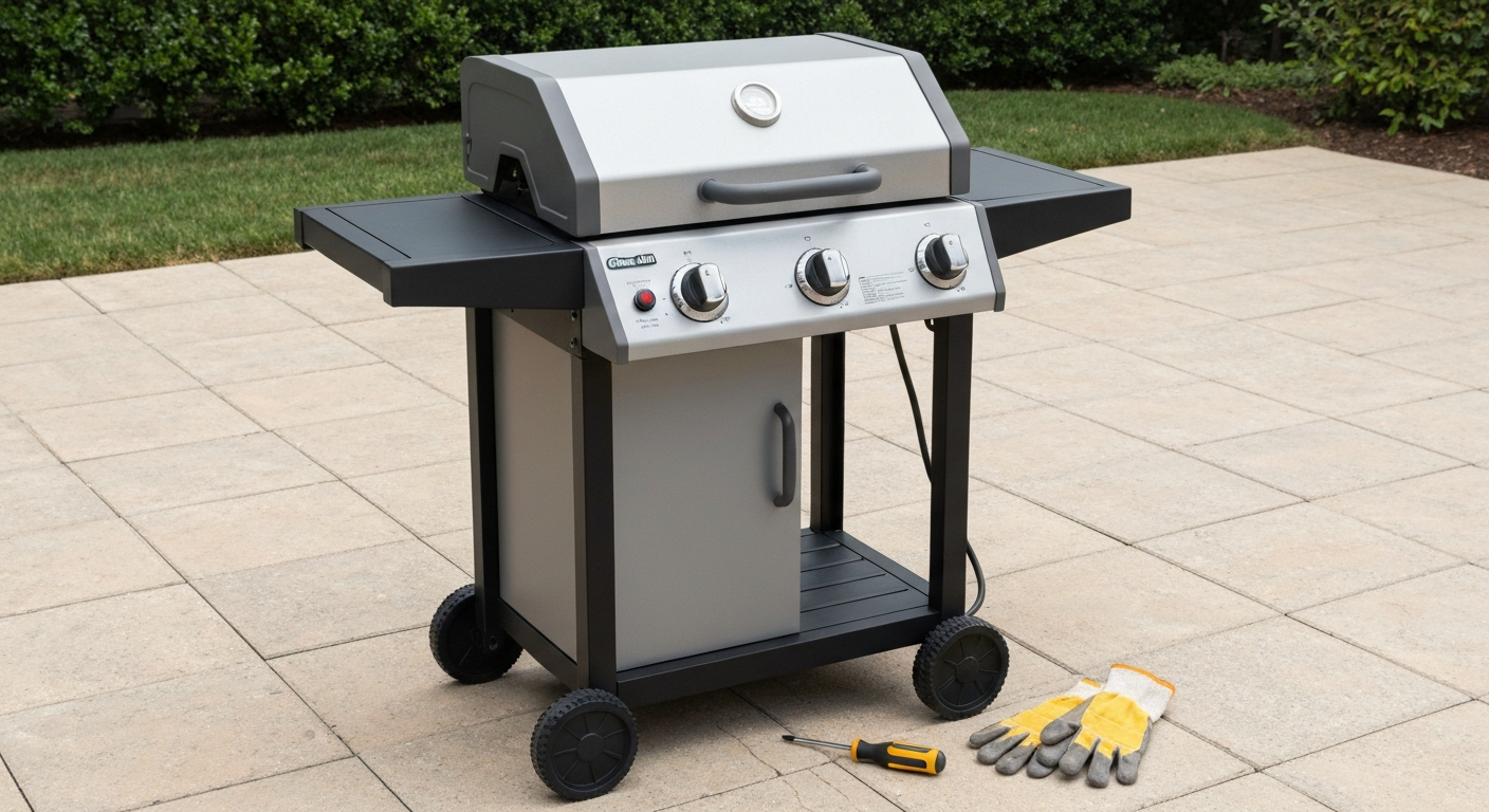
Who this guide is for
This guide is written for homeowners and DIYers who just unboxed a Patio Bistro 240 (common model numbers include 13601860, 12601688-A1, and 16601578) or who are reassembling one after a repair. You need basic hand-tool experience, a flat workspace, and about an hour. You do not need any electrical trade skills for assembly itself, but I will flag the points where electrical awareness matters and tell you when to stop and call a licensed electrician instead of pushing forward.
If your unit is already assembled and you are here because it stopped working, jump to the troubleshooting section near the end. If you need the official Char-Broil manual PDF for your exact model variant, the manual lookup and parts-ordering section at the end covers where to find it.
Safety warnings and electrical precautions
The Patio Bistro 240 draws 1750 watts at 120 volts, which works out to roughly 14.6 amps. That is a substantial continuous load for a household circuit, and Char-Broil's own manual is explicit: plug the grill only into a GFCI-protected outlet. Do not skip this requirement. Most modern outdoor receptacles in the U.S. are already GFCI-protected under NEC Article 210.8, but if you are unsure about your outlet, use a plug-in outlet tester before you ever connect the grill. If your outdoor outlet is not GFCI-protected, have a licensed electrician install one before use.
- Never use a 16-gauge or 18-gauge extension cord with this grill. Char-Broil's manual prohibits this explicitly. If you must use an extension cord, use a heavy-duty outdoor-rated cord (SJTW or SOOW jacket), 12 AWG minimum, kept as short as possible to limit voltage drop under the 14.6-amp load.
- Keep the power cord unplugged during the entire assembly process. Do not plug in until every fastener is tightened, all covers are seated, and the drip tray is in place.
- Do not use the grill on the same circuit as other high-draw appliances. A shared circuit is one of the most common reasons users report GFCI trips after the first few uses.
- The electric Patio Bistro 240 is NOT covered by Char-Broil's gas Patio Bistro electronic ignition recall. That recall applies only to gas models. Do not confuse the two product lines when searching for recall information.
- If you see burn marks, discoloration, or feel heat from the outlet or plug after use, stop using the grill and call a licensed electrician immediately. Same goes for persistent GFCI trips that do not clear when the grill is the only load on the circuit.
When to stop and call a licensed electrician: if your GFCI outlet trips every time you plug in the grill even with nothing else on the circuit, if your breaker trips or runs warm, if the power cord or plug shows any sign of heat damage, or if you need a dedicated 20-amp circuit installed for the grill. These are not DIY fixes. A service call to install a dedicated outdoor GFCI circuit typically costs less than a damaged grill or a house fire.
Set up your workspace before you open the box
A good workspace saves real time during assembly. The Patio Bistro 240 assembles to a width of about 39.8 inches and weighs roughly 54 pounds fully assembled, so you need a sturdy workbench or table at least 4 feet wide and rated for that load. Good lighting matters: the wiring harness connectors are keyed but small, and it is easy to miss a locking tab in poor light. Lay down a moving blanket or thick cardboard on the bench surface before you start, both to protect the porcelain enamel surfaces and to keep small fasteners from rolling away.
Recommended tools and PPE for this assembly:
- Phillips-head screwdriver (medium, #2)
- Flathead screwdriver (medium)
- 10mm and 13mm open-end or box wrenches (or a small adjustable wrench)
- Needle-nose pliers (for snap clips and retaining clips on the wheel axle)
- A rubber mallet or soft-faced hammer (for seating the lid hinges without marring the finish)
- Work gloves: sheet metal edges inside the housing can be sharp
- Safety glasses: especially when working with snap-ring clips on the axle
- A small container or magnetic tray to hold fasteners and keep them sorted by size
Parts checklist: verify every component before you start
Before you lift a screwdriver, unbox everything and lay it out on your padded bench. Match each piece against the parts diagram in your printed manual or the PDF you downloaded from Char-Broil's site. Missing a part now is far less frustrating than discovering it halfway through assembly. Here is what you should find in the box:
| Component | What to check for | Common problem |
|---|---|---|
| Legs (typically 2, with casters on rear) | No cracks in weld points; casters spin freely | Bent legs from shipping pressure on box corners |
| Leg feet / leveling feet | Rubber or plastic caps present and undamaged | Caps missing inside box packaging; check bag |
| Bottom frame / bottom brackets | Straight, no bent flanges | Flanges bent during shipping; straighten before assembly |
| Control housing / side panel | No cracks; knob shaft holes clear of debris | Protective film left on — peel before assembly |
| Control knobs | Correct number per manual; D-shaft inserts fit snugly | Knobs bagged separately; easy to overlook |
| Heating element assembly | Element coil undamaged; element leads not kinked | Leads bent during packing; straighten gently before seating |
| Wiring harness | Keyed connectors intact; no pinched or frayed insulation | Harness folded tightly in packaging; check full length |
| Cooking grates (upper and lower) | Cast-iron or porcelain coating intact; no chips | Chips on edges are cosmetic; cracks near the bars are a return issue |
| Warming rack | No bent bars | Often packed under the grates; check bottom of box |
| Drip tray / grease tray | No deformation; slides smoothly into guide channels | Tray guides can be bent; check guide channels on the housing too |
| Lid with hinge arms | Hinge arms pre-attached and pivot smoothly | One hinge arm sometimes ships loose in hardware bag |
| Hardware bag (fasteners) | Count all fasteners against the hardware list in the manual before starting | Shorted fastener bags happen; easier to call Char-Broil before assembly than after |
If anything is missing or damaged, contact Char-Broil parts support or use the official parts pages for your model number (the website and phone ordering option are both available on their parts site) before proceeding. Trying to improvise with hardware-store fasteners on the structural components is not a safe workaround.
Orientation and layout: how the unit sits before you start building
The Patio Bistro 240 is a freestanding electric grill on a two-leg cart with rear casters and two front fixed feet. The control panel and power cord exit from one side (typically the right side when facing the grill). The lid hinges at the rear. Before you start attaching anything, orient the main housing on the bench with the control panel side facing up and toward you. This gives you clear access to both the leg attachment points and the wiring routing channels without having to flip the unit mid-assembly.
Set the legs and brackets on the bench in the position they will occupy on the finished unit. Left leg on your left, right leg on your right. The leg with the rear casters goes to the back. Keep the hardware bag sorted: longer bolts typically go through the leg brackets at the base, shorter screws typically fasten the housing panels. Do not mix them. Taking two minutes to pre-sort fasteners by size and type at this stage prevents the most common assembly error, which is driving the wrong-length bolt into a panel boss and stripping it.
Step-by-step assembly
Stage 1: Base and frame (legs, feet, and bottom brackets)
Start with the main grill housing placed upside down on your padded bench. Working upside down gives you direct access to the leg attachment flanges without fighting gravity. Locate the bottom brackets (sometimes called bottom side shelves or frame rails depending on your model variant) and dry-fit them first before driving any fasteners. They slot into receiver notches on the underside of the housing and align with pre-drilled holes on the leg tops.
- Position the left and right legs against the housing with the caster legs oriented toward the rear of the unit. The leg tops have slotted or flanged ends that align with the housing's bottom mounting holes. Confirm the orientation by checking that the casters are on the same side as the lid hinge side of the housing.
- Thread the leg mounting bolts in by hand first, all of them, before tightening any. This lets you adjust alignment. If you tighten one leg fully before the other is even finger-tight, you will pull the housing out of square.
- Attach the bottom brackets between the two legs. These provide lateral stability. Align the bracket holes with the matching holes on the lower legs. Thread bolts by hand.
- Now tighten in a cross pattern: snug one leg bolt, then the opposite bracket bolt, then work across. Final torque is firm hand-tight with a wrench, not overtightened. These are typically 10mm or 13mm hex-head bolts depending on your variant.
- Install the wheel axle hardware if your model uses a shared axle rod: slide the axle through the rear caster bracket holes, seat the wheels, and secure with the retaining clips using needle-nose pliers. The manual calls out a 3/8-16 nut on the axle end in some regional variants; if yours uses this, tighten it to snug but do not overtorque, as the axle is not a structural load point.
- Install the leveling feet on the front fixed-foot posts. Twist them on until they contact the bench surface evenly. You will fine-tune leveling once the unit is upright.
- Carefully flip the assembled base upright. Check that all four contact points (two casters, two feet) sit flat on the bench. If the unit rocks, adjust the leveling feet until it sits stable.
Stage 2: Control housing and panel
The control housing on the Patio Bistro 240 contains the thermostat, the power indicator light, and the control knobs. It also routes the wiring harness between the control module and the heating element. Get this stage right and the electrical connection stage that follows becomes straightforward.
- If the control housing is a separate side panel (as it is on most 240 variants), locate the wiring harness exit hole on the main housing body and route the harness tail through it before you mount the control panel. This is the step most people skip, and if you mount the panel first you will have to partially unmount it to thread the harness.
- Align the control housing with the mounting holes on the side of the main body. There are typically four screws (Phillips, medium length) that secure it. Start all four screws by hand before driving any of them.
- Tighten the control housing screws in a diagonal pattern to seat the panel flat against the housing body. If any screw binds before the panel is fully seated, back it out, check for alignment, and reseat. Do not force it.
- Mount the control knobs on the D-shaft posts that protrude through the control panel face. They should push on firmly and align with the printed indicators on the panel face. If a knob spins loosely or the flat of the D-shaft does not engage the knob insert, the knob is on backwards or the wrong knob is on the wrong post. Refer to the manual diagram.
- Route the wiring harness along the inside of the housing in the channel provided. Do not drape it across sharp sheet-metal edges. Keep it clear of any surface that will get hot during operation. Use any factory strain-relief clips or cable guides that are provided in the hardware bag to secure the harness to the housing wall.
Stage 3: Heating element and electrical connections
This is the stage that makes people nervous because it involves electrical connections, but the connections on the Patio Bistro 240 are all keyed plug-in connectors, not bare wire terminals. You are not doing any wiring work. That said, treat this stage with care because a loose or mis-seated connector is the most common cause of a new unit not powering on or heating unevenly.
- With the power cord still unplugged, lower the heating element assembly into the firebox cavity. The element assembly has mounting tabs or bracket ears that align with the inner heat shield mounting points. Seat it fully before making any connections.
- Locate the wiring harness connector(s) coming from the control housing and the corresponding leads on the heating element. The connectors are keyed: they only fit together one way. Do not force a connection that does not align. If it is not sliding together smoothly, rotate 180 degrees and try again.
- Press each connector together until you hear or feel a positive click or seat. On most Patio Bistro 240 variants there are two primary connections: one for the heating element circuit and one for the temperature probe/thermostat circuit. Both must be fully seated.
- Secure any strain-relief fittings where the element leads pass through the housing wall. These are typically plastic saddle clips that snap over the wire at the bulkhead. They prevent the connector from being pulled apart by movement or cord tension.
- Route all wires so they do not contact the heating element body, the inner heat shield, or any surface that reaches operating temperature. The inner heat shield gets very hot. Any wire resting against it will degrade insulation over time and eventually cause a fault.
- Verify cable routing one more time: no pinched wires between panels, no sharp bends at connector points, no wire crossing the element. This is your last easy chance to inspect before the grates and drip tray go in.
- Install the inner heat shield if it mounts separately in your model. It typically screws or clips to the inside of the firebox above the element.
- Set the lower cooking grate in place, then the upper grate or warming rack according to your preference. Slide the drip tray into its guide channels at the base of the firebox. The tray must seat fully in both channels so it does not fall out when the unit is moved.
First power-up: what to check before you cook anything
Before the first cook, do a quick pre-power inspection: lid closes fully, all panels are flush and fastened, drip tray is seated, no tools or hardware left inside the firebox. Plug the unit into a GFCI-protected outdoor outlet with nothing else on that circuit. Turn the temperature control to its lowest setting first, then step up to medium. You should see the power indicator light come on immediately. Within 3 to 5 minutes at medium setting the element should be visibly glowing orange-red when you open the lid briefly. A faint plastic or manufacturing smell during the first 10 to 15 minutes is normal burn-off from the factory coatings and not a cause for concern. If the GFCI trips immediately on plug-in, see the troubleshooting section below before proceeding.
Troubleshooting common faults after assembly
The most common post-assembly and early-use problems on the Patio Bistro 240 fall into a short list, and most of them have a logical diagnostic sequence before you start ordering parts. User reviews and the official manual both document these patterns.
Grill won't power on
- Check the outlet GFCI first: press the reset button on the outlet before assuming the grill is faulty.
- Check the household breaker panel. A 1750-watt load can trip a weak or aging 15-amp breaker, especially if anything else is on that circuit.
- Inspect the power cord plug for any sign of heat damage, bent prongs, or moisture in the prong contacts. Dry completely before retrying.
- If the outlet and breaker are confirmed good and the cord is undamaged, the fault is likely in the control module. This is a Char-Broil replacement part; do not attempt to open or repair the control module yourself.
GFCI trips repeatedly
This is the most commonly reported failure mode from user reviews, often appearing after roughly one year of use. Better Business Bureau entries such as Char‑Broil, BBB customer reviews (examples of part failures, GFI trips, service/backorder issues) document multiple reports of heating element failures, persistent GFI trips, and long repair/parts backorder times Char‑Broil — BBB customer reviews (examples of part failures, GFI trips, service/backorder issues). A GFCI trips when it detects a ground fault, meaning current leaking to ground, which can indicate a degraded heating element, moisture inside the control housing, or a damaged power cord. The diagnostic sequence: first isolate the grill on a dedicated circuit and retry. If it still trips, unplug everything and inspect the power cord and all connector points for moisture. Dry thoroughly (24 hours in a warm, dry space if needed) and retry. If it trips immediately even after drying and isolation, the heating element or control module has an internal fault and the component needs replacement, not repair. Persistent unexplained GFCI trips are a sign you should not keep resetting and retrying; the GFCI is doing its job.
Uneven heating or element not glowing fully
- Verify the element connector is fully seated. A partially mated connector is the most common post-assembly cause of partial heating.
- Check that the thermostat probe connector is also fully seated. A disconnected probe will prevent the thermostat from reading correctly and may cause the element to cycle abnormally.
- If connectors are good and the element still heats unevenly after several uses, the element coil is degrading. Order a replacement heating element assembly through Char-Broil's official parts pages or a compatible third-party reseller using your model number's BOM call-tags.
Control knob spins but nothing changes
If a knob spins freely without resistance, the D-shaft insert inside the knob has sheared or the knob was not fully seated. Pull the knob off and inspect the D-shaft post on the control panel. If the post is intact, replace the knob. If the D-shaft post is sheared at the control module face, the control module itself needs replacement. These are available as OEM parts through Char-Broil's parts site (listed under the thermostat and probe assembly line items in the BOM).
Routine maintenance to keep it running longer
The Patio Bistro 240 does not require much maintenance, but a few habits make a significant difference in how long the heating element and control module last.
- After every cook, let the grill cool completely before covering or storing. Trapping heat under a cover accelerates corrosion of the element and the inner heat shield.
- Empty and wash the drip tray after every use or every two uses at most. Built-up grease in an electric grill's drip tray is both a fire hazard and a source of moisture that can wick toward the element connectors.
- Wipe down the cooking grates with a grill brush or damp cloth while warm, before residue bakes on. The porcelain coating on the grates is durable but not indestructible; avoid wire brushes with loose bristles.
- Inspect the power cord and plug at the start of each season. Look for cracks, stiffness, or discoloration in the cord jacket, and for any discoloration or pitting on the plug prongs. Replace the cord if you see any of these, using only Char-Broil supplied replacement parts as the manual specifies.
- Store the grill in a covered location during the off-season, or use a weather-rated grill cover. Moisture inside the control housing is behind most of the persistent GFCI trip complaints that emerge after winter storage.
- Once per season, check all the structural fasteners (leg bolts, bracket screws, housing panel screws) for tightness. Vibration from outdoor use and movement can loosen them over time.
Finding the official manual and ordering replacement parts
Char-Broil publishes free PDF downloads of operating and assembly manuals for all Patio Bistro 240 model variants, including 13601860, 12601688-A1, and 16601578, through their official support site and manual databases like ManualsLib. If you also own a Patio Caddie gas grill, see the Patio Caddie gas grill manual for model-specific assembly instructions and parts diagrams. You need your exact model number to find the right parts diagram and fastener callouts. The model number label is typically on the inside of the lid or on a sticker on the rear panel of the housing.
For replacement parts, Char-Broil's official parts pages list OEM BOM call-tag identifiers, current pricing, and stock status. Parts for Model Number 12601688-A1, Char-Broil (official site) lists BOM call-tag identifiers, OEM part names, pricing, and current stock status for that Patio Bistro 240 variant Parts for Model Number 12601688-A1 — Char-Broil (official site). Parts commonly needed after a year or two of use include the grease tray, inner heat shield, heating element assembly, and thermostat/probe assembly. Some parts show as out of stock on the official site; in those cases, third-party resellers like eReplacementParts and GrillPartsReplacement list compatible OEM part numbers and cross-reference SKUs that can get you back up and running when Char-Broil's own inventory is backordered. Always verify the part number against your model's BOM before ordering from a third-party source.
If you want a broader look at operating the grill day-to-day once it is assembled, the full Char-Broil Patio Bistro 240 manual covers temperature settings, cooking guidelines, and long-term care beyond what is covered here. And if your unit has stopped working despite a clean assembly, the troubleshooting guide for Char-Broil Patio Bistro not working walks through the diagnostic steps in more detail, including how to test individual components before committing to a parts order.
FAQ
What official manufacturer documents should I consult to create an accurate assembly and service guide for the Char‑Broil Electric Patio Bistro 240?
Primary sources: the Char‑Broil owner’s/assembly manual(s) and official Char‑Broil parts/BOM pages for the specific model number(s) (examples: model 13601860, 12601688‑A1, 16601578). These contain step‑by‑step assembly diagrams, BOM/part call‑tags, fastener callouts, safety warnings, electrical ratings, troubleshooting flow‑checks, and replacement part SKUs. Use the exact model manual matching the unit’s model number and reference the Char‑Broil parts pages for up‑to‑date SKU/stock/pricing information.
Which third‑party/manual-host sources are acceptable to supplement manufacturer docs?
Use reputable manual hosts and parts distributors (ManualsLib, Manuals.plus, ManualZilla) for archived manuals and Char‑Broil regional PDFs for fastener callouts. Use established parts resellers (eReplacementParts, PartSelect) to cross‑reference SKUs and obtain images or alternate‑source pricing. Mark these as secondary sources and confirm any critical discrepancies against Char‑Broil’s official pages.
What electrical and safety standards must be referenced when writing safety guidance for the Patio Bistro 240?
Reference NEC (NFPA 70) guidance for outdoor receptacles (Article 210.8 GFCI requirements and local adoption notes). Cite Char‑Broil’s manual instructions to use GFCI‑protected circuits and prohibitions on undersized extension cords. Advise readers to verify local code adoption dates for NEC updates and to follow manufacturer instructions as the primary product‑specific requirement.
What are the key numerical electrical specifications to include for the Patio Bistro 240?
Include the rated power and typical current: nominal 1750 watts, designed for standard 120 V outlet (≈14.6 A draw). State GFCI requirement per Char‑Broil manual and recommend a properly rated 15 A or 20 A circuit depending on local code and other loads; advise use of a dedicated circuit if repeated trips occur.
Which user‑reported failure modes should the troubleshooting and parts list emphasize?
Emphasize common real‑world failures: repeated GFCI/GFI or breaker trips, thermostat/control‑module failures, heating element/coils degradation or open elements, and intermittent/unresponsive controls. Also note lid‑related heat loss behavior and wear items like grease tray, wheels, and axle hardware.
What pre‑assembly checks and tools should be listed on a workbench‑oriented guide?
Pre‑assembly checks: confirm correct model and complete parts per manual BOM, inspect for shipping damage, lay out fasteners and parts by call‑tag. Tools: common socket/ratchet set (including 3/8 in sizes), combination wrenches, Phillips/flat screwdrivers, pliers, needle nose, adjustable wrench, torque guidance if provided, and a clean flat workbench. Also recommend gloves and eye protection.