If your electric patio heater is plugged in but won't turn on, the most likely culprits are a tripped GFCI outlet, a blown internal fuse, a triggered overheat or tilt cutoff switch, or a dead heating element. Most of these are fixable at home in under an hour with a basic multimeter and a screwdriver. Work through the steps below in order and you will either find the fault and fix it, or get enough information to tell a technician exactly what needs replacing. For more troubleshooting steps specifically for a patio heater not working, see our dedicated guide.
Electric Patio Heater Not Working? Step-by-Step Troubleshooting Guide

Grant Mercer
13 Jul 2026
What this guide covers
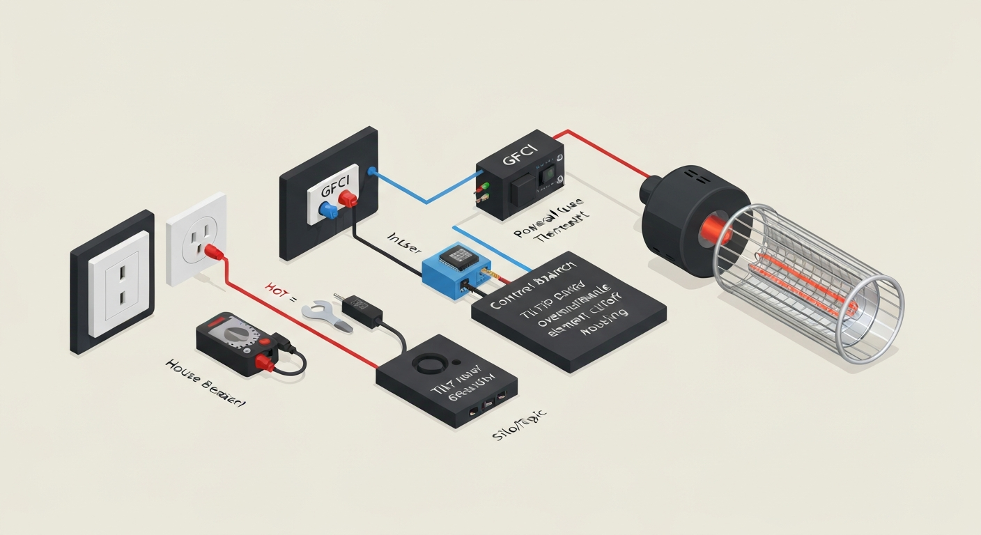
This article is written for homeowners and renters who have a wall-plug or hard-wired electric patio heater that has stopped working and want to diagnose it safely before spending money on a service call or a replacement unit. It walks through every layer of the electrical circuit from the wall outlet inward: the supply voltage, breakers, GFCI protection, the heater's own fuses and cutoff switches, the heating element, and finally remote controls and control boards. It does not cover propane or natural gas heaters in depth, though if you suspect you actually have a gas model (or a combination unit), the troubleshooting path is very different and you should check a guide focused on outdoor propane patio heater issues instead.
Safety checklist and tools you need before you start
Electric patio heaters run on 120V or 240V AC. Both voltages can cause cardiac arrest or severe burns. OSHA's lockout/tagout standard (29 CFR 1910.147) requires that any equipment be fully de-energized and verified at zero energy before servicing. The homeowner version of that rule is simple: unplug the heater or switch off the breaker, then verify the circuit is dead with a meter before you touch any terminal. NIOSH and CDC electrical-safety guidance is equally clear: never assume a circuit is dead based on a switch position alone.
- Electrical-rated insulating gloves (rated for the circuit voltage class, at minimum 1000V for household circuits) and safety glasses
- Insulated screwdrivers and nut drivers
- Digital multimeter (true-RMS, 600V+ AC rating, CAT III or CAT IV safety rating; the Fluke 117 or equivalent is a good benchmark)
- Non-contact voltage (NCV) tester as a quick first check, but always confirm with the multimeter afterward because NCV testers can give false negatives on shielded cables
- Clamp meter if you want to measure running current (true-RMS, rated for at least 20-30A for 240V units)
- Small flathead and Phillips screwdrivers, plus a nut driver set for panel screws
- Replacement fuses matching the heater's internal fuse rating (check the manual or the fuse body)
- Replacement thermal fuse or high-limit cutout if the heater is older or has tripped repeatedly
- New batteries for the remote control
- Camera or phone to photograph wiring before you disconnect anything
A note on live testing: some steps below require measuring voltage with the heater energized. Only do those tests if you are comfortable working near live conductors and are using properly rated gloves and test leads. If you are not comfortable, stop at any live-voltage step and call a licensed electrician. The cost of a service visit is far lower than a shock injury.
Identify your heater before you do anything else
The model number and serial number are almost always on a sticker on the back panel or underside of the heater. On pole-mounted units, check near the mounting collar. On tabletop models, flip the base over. If you're troubleshooting a tabletop patio heater not working, check the compact base area and access panels for tip-over switches and compact wiring that commonly cause failures. Write down the model number and use it to pull the original manual from the manufacturer's website or a manual-lookup service before you proceed. The manual will show you the wiring diagram, fuse locations, and any reset procedures specific to your unit.
Confirm whether you have a purely electric heater or a propane/gas model. This sounds obvious but it trips people up more than you would expect. An electric heater has a power cord or hard-wired conduit connection and no gas valve, no fuel tank connection, and no pilot assembly. A propane heater has a regulator hose. Some combination or 'dual-fuel' products exist. If yours has a gas connection and an igniter that is clicking but not lighting, the problem is on the gas side and this troubleshooting path does not apply. Brand-specific igniter issues on models like Fire Sense and Hampton Bay involve different diagnostics entirely.
Also note the nameplate voltage and wattage. Consumer portable units are typically 120V at 1500W. Larger deck heaters and commercial-grade units are often 240V at 2000-6000W. Some commercial infrared heaters (Bromic, Infratech) run on 208-240V. The rated voltage tells you which outlet type to expect and what multimeter readings are normal.
Quick assessment before you reach for the meter
Answer these four questions first. The answers will tell you which diagnostic step to jump to and save you time.
- Does the heater make any noise or clicking when you press the power button? A click with no heat usually points to a relay or element fault. Silence suggests a power supply or control issue upstream.
- Is there any smell: burning plastic, a musty odor, or a chemical smell? A burning smell means stop immediately, unplug, and inspect for melted wiring or components before continuing.
- Does any indicator light come on, even briefly? A power LED that lights but the heater does not heat narrows the fault to the heating circuit. No LED at all suggests power is not reaching the board.
- Does the remote respond? If pressing buttons on the remote produces a light on the receiver but the heater still does nothing, the receiver is working but the command is not reaching the element circuit. If the remote produces no response at all, start with fresh batteries before anything else.
Step 1: Basic electrical power checks
Start at the wall. Plug a lamp or phone charger into the same outlet to confirm it actually has power. If that device works, the outlet is live. If it does not, you have a dead outlet before you even get to the heater.
With the heater unplugged and the outlet confirmed live, inspect the heater's power cord from the plug to the unit. Look for cuts, kinks, melted insulation, or a plug with blackened or corroded prongs. Any of those findings means replace the cord before proceeding. Do not use a heater with a damaged cord.
Now use your multimeter to verify supply voltage at the outlet with the heater still unplugged. Set the meter to AC voltage, range above 200V for a 120V circuit or above 300V for a 240V circuit. For a standard 120V outlet, you should read approximately 115-125VAC between the hot slot (smaller slot) and the neutral (larger slot), and 115-125VAC between the hot slot and the ground (round hole). For a 240V outlet (NEMA 6-20, 6-30, or 14-30 for example), you should read approximately 240VAC between the two hot terminals and approximately 120VAC from each hot to neutral or ground. A reading below 110V on a 120V circuit or below 220V on a 240V circuit under no load suggests a utility or wiring issue that needs an electrician.
| Measurement point | Expected reading (120V circuit) | Expected reading (240V circuit) |
|---|---|---|
| Hot to neutral | 115-125VAC | 120VAC (each leg to neutral) |
| Hot to ground | 115-125VAC | 120VAC (each leg to ground) |
| Hot to hot (L1 to L2) | N/A | 220-250VAC |
| Neutral to ground | 0-2VAC | 0-2VAC |
| Voltage under load (heater running) | Should stay above 110VAC | Should stay above 220VAC |
Step 2: Breakers, fuses, and GFCI protection
Many outdoor outlets are protected by a GFCI (ground-fault circuit interrupter), either as a GFCI outlet with test/reset buttons on its face, or as a GFCI breaker in the panel. A tripped GFCI is by far the most common reason a patio heater suddenly stops working. Go to the outlet and look for the small test and reset buttons in the center of the outlet face. If the reset button is popped out, press it firmly until you hear a click. Then try the heater again. If the GFCI trips immediately when you plug in the heater, the heater itself has a ground fault and should not be used until the fault is found.
If the outlet has no GFCI buttons, the protection may be at the panel. Open your breaker panel and look for any breaker that is in a middle 'tripped' position rather than fully on or fully off. Reset it by pushing it fully to off first, then back to on. GFCI breakers also have a test/reset button on the breaker face itself.
Internal heater fuses are the next check. Most electric patio heaters have one or more inline fuses inside the heater housing, often in a small fuse holder near the power input or on the control board. Unplug the heater, open the rear panel, and locate the fuse. Set your multimeter to continuity or resistance mode. A good fuse shows continuity (beep or near-zero ohms). A blown fuse shows open circuit (no beep or OL/infinite ohms). Replace a blown fuse with one of exactly the same type and amperage rating. If the new fuse also blows, there is a downstream fault (usually a shorted element or a failed control board) that you need to find before replacing fuses again.
To test GFCI function with a multimeter: with the GFCI reset and the circuit live, measure voltage at the load-side terminals of the GFCI outlet. You should see the same 115-125VAC as the line side. Press the test button. Voltage at the load terminals should drop to zero. Press reset and voltage should return. If the outlet does not interrupt power when tested, the GFCI device itself is faulty and needs replacement.
Step 3: Remote controls and onboard controls
Start with the obvious: replace the remote batteries with fresh ones even if they seem fine. Weak batteries are responsible for a surprising number of 'broken remote' complaints. Use the brand and size specified in the manual, typically AA or AAA alkaline.
If new batteries do not help, check whether the remote and receiver need to be re-paired. Most RF remote receivers have a pairing button or a sequence (hold the remote button within a foot of the receiver for 5 seconds is a common one). Consult your manual for the exact pairing procedure. Westinghouse electric heaters, for example, have a receiver module mounted inside the heater head and require a specific pairing reset if the unit loses its connection after a power outage.
To test the receiver module itself, you need to confirm it is getting input power. With the heater plugged in (and using your PPE), locate the receiver module. It typically receives 12VDC or 5VDC from the control board for its logic circuit, and line voltage (120V or 240V) through its relay output to the element. Set your multimeter to DC voltage and check the low-voltage supply pins on the receiver against the wiring diagram in your manual. A receiver that has no DC supply voltage is not getting power from the board and the fault is upstream. A receiver that has DC power but does not switch the relay when a remote command is sent is a faulty receiver module.
For onboard controls (rotary dial thermostats, push-button panels), a faulty thermostat dial is another common culprit. If the heater works when you bypass the thermostat control during testing (only do this with the power off and reconnect properly afterward), the thermostat is the fault. Replacement thermostat knobs and control assemblies are available from the manufacturer or third-party parts suppliers for most brands.
Step 4: Tilt switches and overheat cutoff switches
Electric patio heaters have two types of safety cutoffs that stop the heater even when power is present: a tilt (tip-over) switch and an overheat (thermal cutout or high-limit) switch. Both sit in series with the heating element circuit, meaning if either one is open, the element cannot get power regardless of what the control board is doing.
Tilt switch: how to find it and test it
The tilt switch is a mechanical microswitch, usually mounted near the heater's base or pivot point. Its job is to cut power if the heater falls over. On tabletop heaters, it is often at the very bottom of the unit underneath a cover plate. On floor-standing pole heaters, check near the base pivot or at the base of the heating head. If the heater was knocked over or stored on its side, this switch may have stuck in the open (tripped) position even after the unit is stood upright again.
To test it: unplug the heater, access the switch, and set your multimeter to continuity mode. With the heater sitting upright and level, the switch should show continuity (closed circuit). If you tilt the heater past its threshold angle (typically 30-45 degrees), the switch should open and continuity should be lost. A switch that shows no continuity in the upright position is stuck open and needs replacement or a mechanical reset (some have a small reset button or plunger). A switch that shows continuity in any orientation is stuck closed and is no longer providing safety protection; it should also be replaced.
Overheat cutoff switch: locate, reset, and test
The overheat or high-limit cutout switch is a thermal device (often a bi-metal strip switch or a one-shot thermal fuse) mounted directly on the heating element or on the element housing. When the element gets too hot (blocked airflow, a dirty reflector, or a failing element drawing too much current), this switch opens to prevent a fire.
Some overheat switches are resettable: they have a small red or black button on their body that pops out when tripped. With the heater unplugged and fully cooled (wait at least 30 minutes), press the button firmly until it clicks. Then reassemble and test. If it trips again quickly, something is causing the element to overheat. Check that the reflector is clean and that the heater's vents are not blocked.
Non-resettable thermal fuses (they look like small glass or ceramic cylinders with wire leads) show continuity when good and open circuit when blown. Test with power removed, multimeter on continuity. A blown thermal fuse must be replaced with an identical part. Do not substitute a fuse with a higher temperature rating because the overheat protection value is calibrated to the element design.
| Switch type | Normal (upright/cool) reading | Tripped/blown reading | Resettable? |
|---|---|---|---|
| Tilt/tip-over switch | Continuity (near 0 ohms) | Open circuit (OL) | Usually yes, mechanically |
| Bi-metal overheat switch | Continuity (near 0 ohms) | Open circuit (OL) | Yes, push button after cooling |
| Thermal fuse (one-shot) | Continuity (near 0 ohms) | Open circuit (OL) | No, must replace |
Testing the heating element itself
If all the switches and fuses check out but the heater still produces no heat, the element is the next suspect. With the heater unplugged, locate the element terminals (usually two wire connectors on the back of the element tube or quartz bulb assembly). Disconnect the wires and set your multimeter to resistance (ohms).
Calculate the expected resistance using Ohm's Law: R = V squared divided by P. For a 1500W heater rated at 120V, that is 120 x 120 divided by 1500, which works out to about 9.6 ohms. At room temperature the actual measured resistance will be slightly lower because resistance increases with temperature, so a reading of roughly 8-12 ohms on a cold 120V/1500W element is normal. For a 240V/1500W element, expected resistance is about 240 x 240 divided by 1500, which equals roughly 38-40 ohms. An element reading open circuit (OL) is burned out and needs replacement. An element reading near zero ohms (short) is also failed and can cause breaker trips or GFCI faults.
Also test from each element terminal to the heater chassis (ground). This should read open circuit. Any measurable conductivity between element and chassis is a ground fault and explains GFCI trips.
Control board faults and when to replace the board
If power is confirmed at the input, switches and fuses all test good, the element checks out, but the heater still does nothing, the control board is likely the fault. Open the heater housing and look at the board with a flashlight. Signs of a failed board include burned or blackened areas, swollen or leaking capacitors, melted connectors, or cracked traces. Any visible burn damage means replace the board.
If the board looks clean, check the board's own internal fuse (most have one). Test it for continuity with power removed. Then, if your manual identifies a DC supply test point (usually labeled VCC or 12V), you can power up the heater and measure that point. A dead DC rail on a board that is receiving AC input means an internal power supply fault on the board. At that point the board should be replaced rather than repaired, because board-level component repair is not practical for most homeowners.
Replacement boards are available from the manufacturer, from appliance parts distributors, and sometimes from the same overseas suppliers used by the brands. Always match the part number from your model's wiring diagram. Westinghouse replacement boards in particular must be model-matched precisely because their wiring harness connectors differ across product generations.
Electric vs propane: making sure you are solving the right problem
It is worth pausing here if the heater has any gas components. If you have a propane model that uses an electric igniter but runs on gas, an electrical fault diagnosis will only get you so far. The igniter circuit in those units is entirely separate from the heat-producing combustion. A dead igniter on a Fire Sense or Hampton Bay propane heater, for example, is a very different repair than a dead heating element in a Westinghouse infrared electric heater. For model-specific troubleshooting, see the Hampton Bay patio heater igniter not working guide for diagnostics tailored to that igniter. For step-by-step diagnostics and common fixes when a Fire Sense igniter isn't sparking, see the guide on fire sense patio heater igniter not working. Gas-side problems (igniter not sparking, thermocouple failures, valve issues) require their own diagnostic path. Tabletop heaters add another layer of complexity because their compact layouts pack the gas valve, thermocouple, and igniter very close together with limited access.
How to decide between DIY repair and calling a pro
Most of the steps above are genuinely DIY-safe for a homeowner who is comfortable with basic hand tools and a multimeter. Replacing a fuse, resetting a GFCI, swapping a thermal cutout, or even replacing a heating element are all straightforward tasks on most heater models. Where the line gets drawn is at hard-wired 240V connections, panel work, or any situation where the fault is not clearly isolated. If you have reached the control board and cannot confirm the fault with a visual inspection and a simple voltage check at a documented test point, calling a licensed electrician or appliance technician is the right call. The NFPA 70E framework that electricians work under exists because energized 240V diagnostics without proper training and PPE carry real risk of injury. NFPA 70E: Standard for Electrical Safety in the Workplace provides guidance electricians use for energized work, safe-energization practices, and classifications that affect how fixed electric space‑heating equipment is treated during servicing NFPA 70E: Standard for Electrical Safety in the Workplace provides guidance electricians use for energized work, safe-energization practices, and classifications that affect how fixed electric space‑heating equipment is treated during servicing..
Also consider warranty status. Many electric patio heaters carry a one- or two-year manufacturer's warranty. If the heater is under warranty and you open it up, you will likely void that warranty. Contact the manufacturer first if the unit is less than two years old. Westinghouse, Bromic, and most mid-range brands have customer support lines that can walk you through whether a repair is covered, where to send the unit, or where to order OEM replacement parts.
Where to get manuals and replacement parts
Start with the manufacturer's website using your model number. If the manual is not there, try the major appliance-manual aggregator sites. For parts, the manufacturer's own parts portal is the safest source for OEM components like thermal fuses and control boards, because aftermarket thermal fuses with incorrect temperature ratings are a genuine safety hazard. For heating elements, branded replacements are preferable but many standard quartz infrared elements are interchangeable by physical dimension and wattage if you verify both measurements match the original. Keep the original part number from the failed component as your reference.
Full diagnostic sequence at a glance
- Gather PPE and tools; photograph wiring before opening anything
- Confirm the outlet has power using a working device or multimeter
- Inspect the power cord for damage; measure supply voltage (expected: 115-125VAC for 120V, 220-250VAC for 240V)
- Check and reset any tripped GFCI outlet or GFCI breaker
- Check the panel breaker; reset if tripped
- Open the heater housing and test internal fuse(s) for continuity; replace if blown
- Test the tilt switch: continuity when upright, open when tipped
- Test the overheat cutout or thermal fuse: continuity when cool; reset or replace if open
- Test the heating element resistance against the calculated R = V²/P value; confirm no ground fault to chassis
- Check remote batteries; re-pair remote and receiver if needed; verify DC supply voltage to receiver module
- Inspect control board for visible damage; test board fuse and DC supply test point
- Replace confirmed failed component; reassemble and retest
- If fault is unresolved or involves panel/hard-wire work, call a licensed electrician
FAQ
What safety standards and official guidance must be consulted before writing troubleshooting steps for homeowners working on electric patio heaters?
OSHA lockout/tagout (29 CFR 1910.147) for de‑energization procedures; NFPA/NFPA 70E guidance for safe electrical work practices and continuous‑load treatment; NEC/Local electrical code for circuit sizing and wiring rules; CPSC guidance on portable electric‑heater hazards and consumer safety recalls. These sources define required controls, permitted work, and when a qualified electrician is required.
Which personal protective equipment (PPE) and tool‑safety requirements should be researched and recommended?
Manufacturer and safety‑agency guidance for PPE: electrically rated gloves and sleeves sized to circuit voltage class, safety glasses, arc‑rated clothing where panel work might be needed. Tool requirements: DMM with True‑RMS, 600V+ rating, CAT III/IV safety category; NCV tester as a preliminary check; appropriately rated insulated hand tools, and clamp meter capable of expected currents. Consult Fluke/test manufacturer PPE/tool guidance and NIOSH/CDC electrical safety pages.
What electrical testing methods and specific measurements must the guide include?
Voltage checks (hot‑to‑neutral, hot‑to‑ground, hot‑to‑hot for 240V) with expected residential values; continuity/resistance tests for heating elements, thermostats, tilt/overheat switches; expected cold‑element resistance calculation using R = V^2/P and example values; clamp‑meter current checks under load; use NCV only as preliminary—always verify with a rated DMM. Sources: NEC/voltage heuristics, Ohm’s Law references, multimeter manufacturer documentation.
Which component‑level diagnostics should be covered and what are the specific test points/readings to look for?
Power supply and branch circuit (breaker, GFCI, fuses): expect ~120VAC or ~240VAC per nameplate; GFCI trips and outlet wiring. Heating element: cold resistance ≈ V^2/P (examples: 1500W@120V ≈ 8–12 Ω). Thermostat/thermal cutouts: NC safety cutouts show continuity at room temp, NO control thermostats open/close per call for heat—test with DMM continuity. Tip/tilt switches: continuity when upright. Control board: input supply voltages, presence of control fuses, visible damage; receiver modules: LED/ pairing diagnostics per manual. Reference service manuals and appliance test guides.
What manufacturer and model information must be located and consulted for accurate instructions?
The unit nameplate (model, serial, rated voltage, wattage), manufacturer service manual, wiring diagram, parts diagram, and published troubleshooting steps. Include brand‑specific notes for common consumer brands (e.g., Westinghouse) and commercial brands (Bromic, Infratech). Use official manuals, OEM parts pages, and reputable manual‑aggregate sites for part numbers and board/element replacements.
What part‑level replacement and reset procedures must be researched and documented?
How to safely reset/replace: local fuses and inline fuses on control boards; GFCI and circuit breaker reset steps; replace heating elements (disconnect power, measure resistance, replace with OEM part, torque/specs for terminals); replace tip/tilt microswitches and thermal cutouts (identify series wiring, use equivalent temp rating); control board and remote receiver replacement (pairing, connector pinout). Consult OEM service manuals for disassembly order, torque, and pairing steps.