
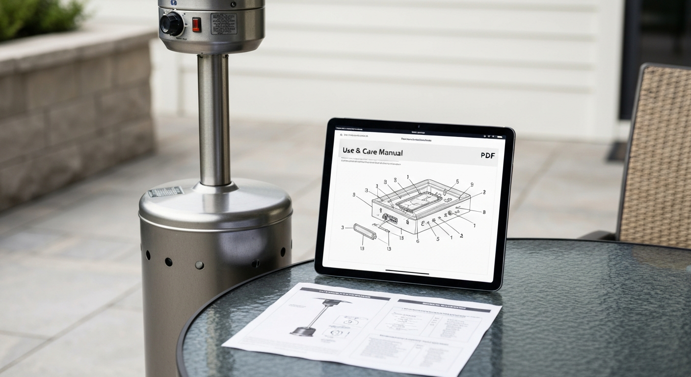
The Sunbeam Patio Master manual you need most likely corresponds to a PG4150H-series gas grill or patio heater, and the official PDF is available through parts vendors like ApplianceFactoryParts and Sears PartsDirect rather than a direct Sunbeam download portal. The core use-and-care manual carries part number 11420161BX, while the assembly sheet is listed as 11412006B and the parts list as 11440655B. If your heater won't light, won't stay lit, or is throwing a weak flame, this guide walks you through the whole process: finding your manual, identifying your model, assembling the unit correctly, connecting gas safely, and fixing the most common faults yourself.
Sunbeam Patio Master Manual: Model IDs, Assembly & Repairs

Grant Mercer
10 Aug 2026
Who this guide is for and what it covers
This guide is written for DIY homeowners who own a Sunbeam Patio Master propane heater or grill and want to handle assembly, routine maintenance, and common repairs without calling a technician. You don't need HVAC training or specialized tools, but you do need to take propane safety seriously. The instructions here are based on the PG4150H series, which is the primary Sunbeam Patio Master platform available through U.S. parts channels. If your unit looks similar but carries a slightly different suffix (PT4150H, for example), the procedures and part numbers overlap heavily, and the manual references both.
The guide covers everything from unboxing and first assembly through gas connection, ignition testing, thermocouple diagnosis, tilt/kill switch faults, regulator checks, and ongoing maintenance. Where a repair genuinely requires a certified gas technician, I'll say so plainly rather than pushing you into a situation that isn't safe for a DIY fix.
Where to find and download the official Sunbeam Patio Master manual
Sunbeam no longer maintains a dedicated consumer portal for Patio Master appliance documentation, so your best option is to go directly to the major appliance parts vendors that host and sell these PDFs. These are the three manual documents you may need, along with their OEM part numbers:
| Document | OEM Part Number | Where to Find It |
|---|---|---|
| Use and Care Manual | 11420161BX (also listed as 11420161) | ApplianceFactoryParts, Sears PartsDirect |
| Assembly Sheet (Sht Instr PG4150H) | 11412006B | ApplianceFactoryParts, CLAGrills |
| Parts List (PG4150H & PT4150H) | 11440655B | ApplianceFactoryParts, Grill-Parts vendors |
To find them: go to ApplianceFactoryParts.com or SearsPartsDirect.com and search for 'Patio Master PG4150H.' Both sites display an indexed parts diagram alongside a separate manuals/documents section. Look for the 'Manuals & Documents' tab or section. Some documents are free PDFs; others are sold as physical sheets for a few dollars. Sears PartsDirect also hosts an exploded diagram view that lets you click individual parts and see their OEM numbers, which is useful even if you already have a printed manual.
Download tips: use a desktop browser rather than mobile for the parts diagram views, since the zoom and click-through features work poorly on small screens. Save the PDF to cloud storage and your phone so you have it at the heater when you're working. If a document shows as unavailable, try CLAGrills.com or Grill-Parts.com using the same part numbers above. They maintain separate inventory and sometimes carry documents that have gone out of stock at the larger portals.
How to find your model number and serial
The product identification plate on Patio Master units is a small metallic or printed label. On grill models it is typically inside the left cabinet door or on the back edge of the bottom shelf. On standalone patio heater configurations, check the control panel housing near the burner valve, and also look on the underside of the base. The label shows the model number (e.g., PG4150H-0), serial number, and gas type. You need both the model and serial when ordering parts, requesting warranty service, or cross-referencing aftermarket components.
- Open the left cabinet door (or access panel) and look on the interior wall near the hinge side.
- Check the back lower edge of the unit, including the shelf underside.
- On freestanding heater poles, check the pole collar just above the base.
- Photograph the label clearly in good lighting before it fades or peels further.
- Write the full model string (including the suffix after the dash, like -0 or -PT4150H) in a notes app or on the inside of the manual cover.
- If the label is unreadable, the parts diagram on Sears PartsDirect lists the full model string in the page URL and header, which you can confirm by matching the physical layout of your unit to the exploded diagram.
Identifying and photographing your parts
Before you order any replacement part or start a repair, spend ten minutes documenting what's actually on your unit. Parts vary even within the same model suffix, and aftermarket suppliers use the model-plus-date-code combination to ship the correct version. Here's what to photograph and why.
| Part | Where to Find It | What to Photograph | OEM Notes |
|---|---|---|---|
| Main burner | Under cooking grates or emitter screen | Full length, both ends, any visible cracks or rust | Cross-reference with burner OEM SKU from parts diagram |
| Gas valve / control knob assembly | Control panel, front of unit | Valve body, inlet/outlet ports, any stamped numbers | Valve body part number is on the diagram; match inlet thread type |
| Regulator and hose | Rear of unit, connects to LP tank | Regulator label, hose length markings, POL or QCC connector type | Most PG4150H units use a QCC1 (Type 1) connector |
| Thermocouple | Pilot assembly, tip positioned in pilot flame | Tip position, wire routing, connector at valve end | Measure wire length before ordering replacement |
| Tilt / kill switch | Inside base housing, near base plate | Switch body, wiring connector, mounting bracket | Labeled 'tip-over switch' in some parts diagrams |
| Ignition assembly | Control panel or side, spark electrode at burner | Electrode tip gap, wire color and connector, battery compartment | PG4150H uses a push-button ignitor; spec ~12 kV output |
Take photos in natural daylight if possible. For the thermocouple and ignition electrode, use your phone's macro mode to get a sharp close-up of the tip and the connector at the valve end. A blurry photo of a thermocouple connector won't tell you whether you have a push-in or spade-lug fitting. These details matter when you're on a parts site at midnight trying to order the right replacement.
Tools and safety equipment you'll need
Most assembly and diagnostic work on the Patio Master requires only basic hand tools. For gas-related procedures, you also need a few inexpensive safety items. Do not skip the safety items. Propane burns at roughly 3,600°F and is denser than air, which means a leak pools at floor level invisibly. A multimeter and leak-detection solution are not optional extras.
- Phillips and flat-head screwdrivers (medium and large)
- Adjustable wrench and a set of open-end wrenches (3/8" to 3/4")
- Needle-nose pliers
- Digital multimeter (for thermocouple and ignition testing)
- Manometer (optional but useful for verifying regulator output pressure; borrow or rent if you don't own one)
- Leak-detection solution or liquid dish soap mixed with water in a spray bottle
- Teflon (PTFE) tape rated for gas fittings (yellow tape, not white plumbing tape)
- Safety glasses
- Nitrile gloves
- Fire extinguisher rated ABC, within arm's reach during any gas-related work
- Flashlight or headlamp for inspecting inside the base and cabinet
A torque wrench is helpful but not strictly required for assembly. Most fittings on this unit are hand-tight plus one-quarter turn with a wrench. Where the manual specifies a torque value, follow it. For ignition electrode gap setting, a feeler gauge or even a folded business card (roughly 4 mm) gives you a workable reference, since the target gap is 4 to 6 mm for the spark module used on the PG4150H series.
Pre-assembly inspection and site preparation
Whether you're assembling a new unit or reassembling after a repair, run through this checklist before you pick up a wrench. Skipping this step is how people end up with a bag of leftover hardware or a gas connection that wasn't seated properly.
- Unbox on a clean, flat surface outdoors or in a well-ventilated garage. Never assemble a gas appliance in an enclosed space.
- Lay out all parts and match them against the parts list (document 11440655B). Count fasteners now, not halfway through assembly.
- Inspect the burner, valve body, hose, and regulator for visible cracks, kinks, or corrosion from shipping or storage. Do not proceed if the hose has a kink or crack.
- Check the regulator for the correct connector type: the PG4150H uses a QCC1 (Type 1) fitting that requires an OPD-equipped cylinder. Older POL-style cylinders need an adapter — but it's simpler and safer to just use a current OPD cylinder.
- Confirm your LP cylinder has fuel and is upright on a flat, stable surface at least 3 feet from any structure or ignition source.
- Choose an assembly site away from foot traffic so you can leave the unit in place while you test. The final operating site should be on a flat, non-combustible surface at least 3 feet from walls, overhangs, and combustibles.
- Keep a bucket of water and your ABC fire extinguisher nearby during gas connection and initial lighting.
- Read the full assembly sheet (11412006B) once through before starting. Identify any steps specific to your suffix variant.
Full assembly and setup, step by step
The following steps follow the PG4150H assembly sheet sequence. If your unit has a slightly different panel layout, the exploded diagram on Sears PartsDirect will show the correct fastener positions for your specific suffix.
Frame and base assembly
- Attach the left and right side panels to the firebox body using the provided carriage bolts and wing nuts or hex bolts per the diagram. Start all fasteners by hand before tightening any of them. This keeps the frame square.
- Attach the bottom shelf bracket, then slide the shelf into position. Confirm it sits level before fully tightening the shelf bolts.
- Attach the cabinet doors (if present) by seating the hinge pins from the top. Do not overtighten the door stop screws or the doors won't swing freely.
- Install the leg assemblies or base casting. If your model has casters, lock them now and confirm the frame doesn't rock on the surface before proceeding.
Burner and firebox installation
- Lower the main burner into the firebox, aligning the burner inlet tube with the valve orifice port. The inlet tube should slide over or around the orifice without forcing. If it binds, check that the orifice hasn't shifted.
- Secure the burner with its mounting bracket or retaining clip per the parts diagram. The burner must not shift side to side.
- Install the tilt/kill switch in its mounting bracket inside the base housing before closing up the base. Route the wiring away from any moving parts or heat sources.
- Install the ignition electrode into its bracket so the tip sits 4 to 6 mm from the burner surface or dedicated spark point. This gap is critical: too wide and it won't spark reliably, too narrow and the electrode can foul.
- Route the ignition wire to the push-button module and connect it firmly. For models with a battery-powered ignitor, install a fresh AA or AAA battery per the parts sheet notation before testing.
Control panel and valve assembly
- Mount the valve/manifold assembly to the firebox per the diagram. Hand-tighten the mounting bolts first to allow minor positional adjustment.
- Attach the control knobs to the valve stems. Most knobs are a push-and-turn fit; align the flat on the stem with the flat inside the knob before pressing.
- Install the burner control knob labels if your unit ships with adhesive label overlays. Apply them before you close up the panel.
- Finalize all panel fasteners to snug. Do not strip the sheet-metal screws on the control panel; they don't need to be overtightened.
Emitter screen and top assembly
- Place the heat shield or emitter screen above the burner per the diagram. It should sit level and not contact the burner surface directly.
- Install cooking grates or the radiant emitter assembly. Confirm they are fully seated on their support rails and do not wobble.
- Attach the lid or top cap if your model has one, aligning the hinge brackets before inserting the hinge pins.
- Do a final visual inspection: no wires pinched by panels, no burner tube misaligned, all fasteners snug.
Gas connection and regulator setup
This is the most safety-critical part of the entire setup. Read this section completely before touching the LP cylinder valve. Work outdoors only. No open flames, lit cigarettes, or sparks in the area.
Connecting the regulator and hose
- Confirm the control knob on the heater is in the OFF position before connecting anything.
- Inspect the regulator hose for cracks, abrasions, or kinks. A damaged hose must be replaced before any gas connection. Use an OEM or compatible replacement rated for LP service.
- Orient the regulator so the vent hole (a small hole or slot on the regulator body) faces downward or sideways, never upward. An upward-facing vent can allow moisture or debris inside, causing pressure errors.
- Thread the QCC1 connector onto the cylinder valve hand-tight, then tighten with a wrench until snug (roughly one-quarter turn past hand-tight). QCC1 connectors have a right-hand thread. Do not use Teflon tape on QCC1 fittings; the seal is mechanical.
- Connect the hose to the valve inlet fitting on the heater body. If this fitting uses a flare-to-pipe adapter, apply yellow PTFE gas tape to the pipe-thread end only, not the flare end.
- Open the LP cylinder valve slowly, one full turn counterclockwise. Listen and smell for any gas odor. If you smell gas, close the cylinder valve immediately, move away from the unit, and do not proceed until you have identified and corrected the leak.
Leak testing every connection
This step is mandatory, not optional. Apply your soapy water solution or commercial leak-detection fluid generously to every fitting: the QCC1 connection at the cylinder, both ends of the hose, and the hose-to-valve fitting at the heater. Watch for bubbles forming. Even slow, small bubbles indicate a leak that must be fixed before lighting. Never use an open flame to check for leaks. After testing, rinse off the soap with clean water so it doesn't degrade the rubber fittings over time.
Regulator pressure and what to expect
The regulator on the PG4150H series is designed to deliver approximately 11 inches of water column (about 0.39 psi or 2.74 kPa) at its outlet. This is the standard working pressure for residential LP appliances per typical OEM specifications and is the pressure at which the burner orifice and manifold are calibrated. If you ever test outlet pressure with a manometer and get a reading significantly below 11" WC under normal flow, the regulator is likely faulty or the cylinder is nearly empty. High readings above roughly 13" WC suggest regulator failure in the open direction, which is a fire hazard. In either case, replace the regulator before using the unit.
A note on OPD cylinders: the PG4150H manual and general LP safety requirements call for cylinders equipped with an Overfill Protection Device (OPD). These have a triangular handwheel and a QCC1 (Type 1) outlet. If your cylinder has a round or flat handwheel and a POL (left-hand thread, plugged) outlet, it predates the OPD requirement and should be taken to a propane dealer for replacement. Using non-OPD cylinders on current appliances is a safety and compliance issue, not just a technicality.
First lighting and ignition check
- Open the LP cylinder valve fully (counterclockwise until it stops, then back a half-turn to prevent the valve from sticking in the open position).
- Turn the control knob to the 'IGNITE' or 'START' position and depress it fully if your model requires pressing to open the safety valve.
- Press the piezo push-button ignitor repeatedly (up to 10 times) while holding the knob depressed. You should hear clicking and see a spark at the electrode.
- Once lit, hold the control knob in the depressed position for 15 to 30 seconds to allow the thermocouple to heat up and signal the valve to stay open.
- Slowly release the knob. The flame should remain lit. If it goes out immediately, the thermocouple needs more heat time or is failing (see the thermocouple section below).
- Adjust to your desired heat setting and observe the flame for two to three minutes. A healthy flame on a propane burner is mostly blue with small orange tips. A predominantly yellow or orange flame suggests incomplete combustion, which may mean the air shutter needs adjustment or the burner orifice is partially blocked.
Troubleshooting: when the heater won't light or stay lit
Most Patio Master ignition failures trace back to four causes: a dead ignitor, a fouled electrode, a failed thermocouple, or a tripped tilt/kill switch. Work through them in order before assuming you need a new valve or burner. Other propane heater brands like the Thermo Tiki and Bali Outdoors portable models share this same diagnostic sequence, so the logic here transfers broadly.
No spark at all
- Check the battery in the ignitor module first. Replace it with a fresh one and test again. A weak battery is the most common cause of no-spark complaints.
- Inspect the electrode tip. Carbon buildup on the ceramic insulator creates a short that kills the spark. Clean the tip with fine emery cloth or a wire brush, then test again.
- Check the electrode gap. It should be 4 to 6 mm. Close the gap with needle-nose pliers (bend the ground tab slightly toward the electrode tip) if it has opened up.
- If you still get no spark, use a multimeter to check for continuity in the ignitor wire from the push-button module to the electrode connector. A break in the wire is easy to overlook if the wire runs through a panel and has been pinched.
- The push-button ignitor module on the PG4150H is rated at approximately 12 kV output. If the module itself has failed, you can confirm this by testing it in open air: hold the electrode a few millimeters from a ground surface (the metal frame) and press the button. No spark means the module is dead. Cross-reference the module OEM number for a compatible replacement from GrillRepairParts or CLAGrills.
Spark present but burner won't light
- Confirm gas is flowing: turn the knob to the start position and briefly smell near the burner ports. You should detect a faint gas odor within a few seconds. If not, the valve may not be opening, or the tilt switch has interrupted the circuit.
- Check the tilt/kill switch. Locate it inside the base housing. It should be in its normal upright position. If the unit was tipped or roughly handled, the switch may have tripped and latched. Reset it per the parts diagram or by pressing the reset button if your model has one.
- Check for spider webs or debris blocking the burner ports. Insects, particularly spiders, nest in the venturi tubes during storage. Disconnect the gas, remove the burner, and inspect the venturi inlet and all ports. Clear any blockage with a pipe cleaner or compressed air (not a wire, which can enlarge the orifice).
- Confirm the electrode spark position is directly adjacent to a burner port, not between ports. Repositioning the electrode bracket by a few millimeters can make the difference.
Lights but won't stay lit: thermocouple diagnosis
If the heater lights when you hold the control knob down but goes out the moment you release it, the thermocouple is the primary suspect. The thermocouple is a safety device: its tip sits in the pilot flame, and the heat it generates produces a small millivolt signal that tells the gas valve it's safe to stay open. When the thermocouple cools down (or fails), the valve closes automatically.
- With the heater off and gas disconnected, set your multimeter to millivolts (DC).
- Disconnect the thermocouple lead from the gas valve connection point. Note whether it's a push-in or threaded fitting.
- Reconnect the gas, light the pilot, and hold the control knob down for 60 seconds to fully heat the thermocouple tip.
- With the pilot burning, measure the millivolt output across the thermocouple wire and its ground. A healthy thermocouple produces roughly 25 to 35 millivolts. A reading below 10 to 15 millivolts indicates the thermocouple is marginal or failing.
- If the reading is low, try repositioning the thermocouple tip so it sits deeper in the pilot flame before replacing it. Sometimes the tip has shifted and is only catching the edge of the flame.
- If the reading remains below 15 mV with the tip correctly positioned, replace the thermocouple. Match the wire length and connector type from your earlier photo documentation. Universal thermocouples are available at hardware stores; the OEM number from the parts diagram will get you an exact fit.
Weak or low flame: regulator and orifice checks
- First, check the LP cylinder. A nearly empty cylinder produces reduced pressure and a weak flame even with a working regulator.
- Check for the 'regulator lock-up' condition: if you opened the cylinder valve while the heater control was in the open position, some regulators trip an internal safety mechanism that restricts flow. Close the cylinder valve, turn the heater knob to OFF, wait 30 seconds, then reopen the cylinder valve slowly and attempt lighting again.
- If the flame is consistently low across multiple lighting attempts, connect a manometer to the regulator outlet port and verify you're getting 11" WC output under normal flow. A reading significantly below this means the regulator needs replacement.
- Inspect the main burner orifice for partial blockage. The orifice is a precisely sized brass fitting at the burner inlet. Do not use a wire or drill bit to clean it; use a wooden toothpick or compressed air only. A damaged orifice changes the fuel-air ratio and must be replaced with an OEM-matched part.
Tilt switch: testing and resetting
The tilt or tip-over switch is a safety feature that cuts gas flow if the unit tilts beyond a set angle. It's a small mercury or mechanical switch mounted inside the base housing on a bracket. On Patio Master units it's sometimes called the 'kill switch' in aftermarket parts listings. If your heater suddenly stopped working after being moved, bumped, or placed on uneven ground, this is the first thing to check.
- Make sure the unit is on a level, stable surface. The switch will not reset correctly on an uneven floor.
- Open the base access panel or remove the base cover per the parts diagram.
- Locate the tilt switch on its mounting bracket. It should sit in its normal position (not obviously tilted or displaced).
- Use a multimeter set to continuity mode. Disconnect the switch wiring connector and test across the switch terminals. A correctly positioned switch should show continuity (closed circuit). If it shows open circuit while the unit is level, the switch has either tripped and latched or has failed.
- Some models have a manual reset button on the switch body; press it once firmly. If the switch won't reset and the unit is level, replace the switch. It's a low-cost part and is available cross-referenced to Patio Master / Sunbeam applications through GrillRepairParts.
- After reconnecting or replacing the switch, retest the full circuit by attempting to light the heater normally.
Replacing common parts: what you need to know
Most repairs on the Patio Master come down to four replaceable components: the thermocouple, the ignitor module/electrode, the regulator and hose, and occasionally the main burner. Aftermarket vendors document cross-compatibility; for example, Push Button Igniter with Side Burner, GrillRepairParts (Patio Master / Sunbeam cross‑reference listings) lists igniter kits and compatible Patio Master/Sunbeam SKUs Push Button Igniter with Side Burner — GrillRepairParts (Patio Master / Sunbeam cross‑reference listings). Here's what to know before you order.
| Part | When to Replace | OEM or Aftermarket | Notes |
|---|---|---|---|
| Thermocouple | Output below ~15 mV or heater won't stay lit after repositioning | Universal 24" millivolt thermocouple works in most cases; OEM is preferred | Match wire length and valve-end connector type |
| Ignitor module | No spark after battery change and electrode cleaning | Aftermarket 12 kV push-button units are compatible; confirm wire count | Cross-reference via GrillRepairParts Patio Master listing |
| Electrode tip | Cracked ceramic, corroded tip, gap won't hold | OEM from parts diagram; aftermarket if dimensions match | Confirm tip-to-burner distance on reinstall |
| Regulator and hose | Regulator won't hold 11" WC, hose cracked or kinked | Replace as an assembly; do not repair hoses | Use LP-rated hose; confirm QCC1 connector type |
| Main burner | Cracked, rusted through, ports uncleanable | OEM from Sears PartsDirect or ApplianceFactoryParts by model suffix | Check venturi alignment on reinstall |
| Tilt/kill switch | Fails continuity test on level surface | Aftermarket cross-referenced to Patio Master / Sunbeam | Mount at correct angle per original bracket orientation |
When ordering aftermarket parts, always provide the full model string including the suffix (PG4150H-0, not just PG4150H). Some parts vendors stock multiple versions and will ship the wrong one if you don't specify. The parts list document (11440655B) gives you the OEM numbers to use as a cross-reference even when buying aftermarket.
Routine maintenance and seasonal checklist
A Patio Master that gets a 30-minute annual inspection will outlast one that gets ignored for years. These tasks take minimal time and prevent most of the failure modes described above.
Before each heating season (spring or fall startup)
- Inspect the regulator hose for cracks, brittleness, or UV degradation. Replace if in doubt.
- Leak-test all gas connections with soapy water before the first use of the season.
- Remove the burner and clear the venturi tubes of spider webs and debris with a pipe cleaner.
- Clean the burner ports with a soft brush; do not enlarge them with metal tools.
- Check the electrode tip gap (4 to 6 mm) and clean carbon deposits from the ceramic.
- Test the tilt switch for continuity while the unit is level.
- Verify the thermocouple tip is correctly positioned in the pilot flame path.
- Check all structural fasteners on the frame and base for looseness.
After each use
- Turn the control knob to OFF and close the LP cylinder valve. Do not rely on just one shutoff.
- Allow the unit to cool fully before covering or storing.
- Use a weather-resistant cover to protect the regulator and hose from UV and moisture.
- Store LP cylinders upright outdoors, never inside a cabinet, garage, or enclosed space.
Annual deep clean
- Wash emitter screens and heat shields with warm water and mild soap; rinse thoroughly.
- Inspect the firebox interior and base for corrosion, especially at weld points and the base casting.
- Check all wiring for heat damage, cracked insulation, or loose connectors.
- Inspect the gas valve for external corrosion or physical damage. Do not attempt to service the valve internally; replace it if damaged.
- Verify the product identification label is still legible and photograph it if it has faded.
Safety standards and compliance
The Sunbeam Patio Master series is designed to conform to ANSI Z21. ANSI Z21.58 / CSA 1.6 is the American/Canadian standard covering outdoor cooking gas appliances and their labeling, installation, and pressure requirements (CPSC, Z21/CSA Joint Technical Subcommittee on Standards for Outdoor Cooking and Illuminating Gas Appliances, PDF). 58 / CSA 1.6, which is the standard covering outdoor cooking gas appliances. Your local installation may also fall under ANSI Z223.1 / NFPA 54 (National Fuel Gas Code) and NFPA 58 (LP-Gas Code), depending on jurisdiction. These aren't just regulatory footnotes: they define the clearance distances, cylinder storage rules, and pressure requirements that are baked into the OEM manual's instructions. When this guide says '3 feet from combustibles' or 'OPD cylinder required,' those numbers come from these standards. If you're in a jurisdiction with specific outdoor appliance regulations, check with your local authority before installing in a covered patio or pergola.
Warranty and manufacturer contact
Sunbeam's Patio Master products were distributed under the Sunbeam / Jarden Consumer Solutions umbrella, which is now part of Newell Brands. Warranty claims and direct manufacturer support for legacy Patio Master models are handled through Newell Brands customer service. The warranty period for most Patio Master grills and heaters was one year on parts and labor from original purchase date, with some extended coverage on specific structural components. To make a warranty claim, you need the model number, serial number, and proof of purchase. Contact Newell Brands consumer services directly via the Sunbeam brand page at sunbeam.com, or call 1-800-458-8407. For parts that are out of warranty, the vendor sources listed earlier (ApplianceFactoryParts, Sears PartsDirect, CLAGrills) are the practical replacement channel.
When to stop and call a professional
Most of what's covered in this guide is genuinely within DIY reach. But there are a few situations where the right call is to stop and get a certified gas technician involved. If you smell gas and can't identify the source after a full leak test of all external connections, the leak may be internal to the valve assembly. Do not attempt to disassemble or repair a gas valve internally. If your manometer shows regulator pressure wildly outside the 11" WC range and a new regulator doesn't fix it, there may be a supply-side issue with your propane tank or fill level that needs a propane dealer's attention. And if the unit has been involved in a fire, flood, or significant impact, have it inspected by a professional before returning it to service, regardless of how it looks externally.
Other patio heater manuals worth bookmarking
If you're working on a different unit or comparing features across brands, the same diagnostic logic in this guide applies to other popular propane heaters. The Thermo Tiki outdoor propane patio heater and the Bali Outdoors portable patio heater both use similar thermocouple-and-tilt-switch safety circuits, so the millivolt testing procedure and tilt switch continuity check translate directly. For model-specific details refer to the Thermo Tiki outdoor propane patio heater manual for troubleshooting steps and part numbers. For model-specific diagrams and replacement parts, see the Bali Outdoors portable patio heater manual. The Belleze patio heater and Infinity Glo patio heater use comparable push-button ignition assemblies. See the Infinity Glo patio heater manual for model-specific details on the push-button ignition assembly and parts references. For model-specific diagrams and parts lists, see the Belleze patio heater manual (internal reference 93be08b6-a039-42bf-9f69-c7f13bec23d2). If you have a smaller unit, the Cuisinart tabletop patio heater manual covers a scaled-down but functionally similar gas system. The Tall Mocha Mainstays patio heater and quartz glass tube heater instruction manual cover the standing-column style with radiant emitters, which adds a few different maintenance considerations around the emitter screen and quartz tube inspection. If you need its documentation, look specifically for the Tall Mocha Mainstays patio heater manual on appliance manual or parts sites to download the model-specific assembly and maintenance instructions. If you need the quartz glass tube patio heater instruction manual, search the major parts vendors and manual archives for that exact title to find the OEM PDF or parts diagram.
FAQ
Which official documents and vendor resources must I obtain to create an accurate Sunbeam Patio Master manual/repair guide?
Obtain the OEM 'Use & Care' and assembly PDFs for Patio Master / Sunbeam models (example part numbers 11412006B, 11420161BX, 11440655B), exploded parts diagrams and parts lists (Sears PartsDirect, ApplianceFactoryParts), and retailer-supplied sheet instructions/parts lists (CLAGrills, Grill-Parts). Save copies of any manufacturer safety labels or OPD/cylinder warnings.
What model- and serial-identification facts should the guide tell homeowners to collect?
Explain how to locate the product identification plate (control panel, inside cabinet door, back edge of bottom shelf), what fields to read (model number, serial number, manufacture date), and why these are required for ordering the correct manual and parts.
Which authoritative specifications about fuel and regulator pressure are essential to include?
Include the required LP regulator outlet pressure (typical OEM target ≈11" water column), allowable tolerances where published, the need to use an OPD-equipped cylinder where specified, and instruction to verify regulator type and orientation per OEM documentation.
What electrical/ignition specifications and test values must be documented?
Document ignitor type (battery or electronic spark generator), battery voltage and recommended electrode gap, and typical spark generator output range (product specs commonly list ~12 kV). Provide safe testing steps (visual spark test with covers removed, battery checks, continuity checks) and part cross-references for ignitor modules.
What thermocouple and thermopile test values and procedures are required?
Provide thermocouple open-circuit voltage guidance (healthy ~25–35 mV; marginal below ~10–20 mV), stepwise test procedure with a multimeter while heating the pilot, and pass/fail thresholds and recommended replacement part IDs.
Which regulator and gas-flow tests should the guide explain?
Include manometer hookup and outlet-pressure verification (target ≈11" WC), how to check regulator 'creep' and isolation leaks, and steps to swap with a known-good regulator. List common replacement regulator SKUs and safety cautions about over-tightening fittings.